Secrets of Tire Changing Revealed!

Hi Killa’s Garage fans! Today’s post is a bit more practical than some of my others. In fact it might not be esoteric enough to qualify as an esoteric observation on bicycles and cycling, but I’ve been wanting to talk about this topic for a while now. I will attempt to describe how I change a bicycle tire, without using tire levers.

Watching someone remove and install a tire without tools is a bit like watching a magic trick. You can see it being done, and it looks easy. But it doesn’t work when you try it. I’ll break the magician’s code and tell you how it’s done.

This is not another start-to-finish instructable. If you want to watch a video on changing a tire, Google “bicycle tire change”.  What I’ll do is reveal the four key techniques I use that make it look easy.

I know there are a few different ways to approach this problem, and this is just the way I do it. Here are my secrets:

  1. Talcum Powder, Lots of Talcum Powder

In the garage I keep a large container of talcum powder (Johnson’s baby powder if you must know). I sprinkle it generously on any new tire and tube before assembly. It helps the tube slide into a comfortable position inside the tire, and it helps the tire slide over the rim rather than gripping it and fighting me.

When I pack my spare tubes for the road, I put them in a Ziploc bag with a generous dose of baby powder. It makes the new tube easier to install, and it gives my seatpack a nice fresh scent.

I once made the mistake of using corn starch. Did you know that corn starch makes a pretty good glue when it gets wet? Continue reading “Secrets of Tire Changing Revealed!”

What’s That @#$% Noise, Part Two

Here’s part two of “What’s That @#$% Noise”. This was meant to be a one episode thing, but my list kept growing. I’d like to thank my friends who kept reminding me of various vicious noises we’ve worked on through the years.

Continuing in no particular order:

Bottom Bracket – Bearings

A lot of noises sound like they are coming from the bottom bracket. Many times the source is somewhere else, but sometimes it is the bearings. Last week Virgil brought over his bike with a creaking whenever he pushed down hard on the left pedal. We pried the outer seal off the left bearing (Shimano) and it was all rusty brown inside. But it was ten years old! I’d call that a good run.

Modern sealed bottom bracket bearings are amazingly durable. I have found Shimano external threaded bearings especially long-wearing, as were their prior generation of cartridge bottom brackets. Recently Shimano reduced the size of their bearings, presumably to shave weight. We’ll see if they are still as durable. Early failure on some of the other brands of external bearings is not uncommon in my experience.

Often a failed bearing can be felt as a looseness while pushing a crankarm side to side. Roughness or looseness can also be felt by removing the crank and turning the bearings by hand.

Bottom Bracket – Frame Interface

I’ll say it right up front. I am no fan of press-fit bearings. There are so many issues that don’t exist with a threaded interface. There are two advantages to press-fit in its various forms: 1. It allows the use of a larger OD crank spindle, and 2. It allows frame designers to stiffen the bottom bracket area by making it wider. These are real advantages. But they are offset by one serious disadvantage. An effective (noiseless) press-fit must be machined to a very high level of precision. Machine a precision bore into carbon fiber or aluminum, then press a hardened steel bearing into it, ride a couple thousand miles, bang the bearing out and replace it. Repeat this a few times and your precision interface is not so precise, if it ever was.

For Trek bikes, there is even a 0.1mm oversize bearing set to accommodate frames that were initially too loose or become so.

trek-oversize-bearing

Creaking press-fit bottom brackets are so ubiquitous that there is a market for kits to convert to a threaded torque-able interface.

Threaded bottom brackets can creak too, if the threads are dry or insufficiently torqued. But I know how to fix that.

Truth in blogging admission: Even in threaded bottom bracket designs, the bearings are press-fit into the threaded cups. But, it’s a lot easier to manufacture a precision small part, like a cup. And the bearing only has to be pressed in once. Continue reading “What’s That @#$% Noise, Part Two”

Quick Tip: McGyver’s Lip Balm

In keeping with the @#$% noises theme, I had a McGyver moment last weekend and I wanted to write a quick post to share it with you.

My best friends and I were riding  Katy Cycling Club‘s No W(h)ine Tour in the Texas Hill Country when my derailleur cables developed a squeak where they pass under the bottom bracket. The cable guide was dry from a previous ride in the rain, and maybe a little Gatorade had dribbled down the cables. Anyway, every shift was accompanied by a wretched squeak, made all the more embarrassing by the fact that it was the mechanic’s bike making all the noise. And my shifting was none too good either.

I was pondering where I could get a dab of grease or oil. I considered buying a bag of potato chips and rubbing one on the cables, or asking a motorist if I could have a drop of oil from their dipstick. Then I remembered my ChapStick. So I ate my chips, flipped the bike over, and gave both cables a swipe of lip balm where they pass over the cable guide. Silent shifting for the rest of the day.

I’m still working on part two of my @#$% noises compendium, coming soon. Friends are reminding me of noises I had forgotten about, like the Banshee free-hub…


What’s that @#$% Noise!?!?

It’s been a while since I posted. I’ve been working on this compendium of annoying bicycle noises for over a month. The list keeps growing faster than I can write, so I’m gonna publish this “part one” and keep working on the rest.

Don’t you hate it when your bike is making a clicking, or creaking, or ticking, or buzzing noise and you can’t figure out what it is? I do! It’s especially annoying on carbon fiber bikes and wheels because they seem to amplify noises and echo them all over the bike. I’ve heard a lot of noises, and I’ve been able to run most of them down. I’ve also heard about some weird ones from friends who have been able to eliminate them.

One of the keys to finding the noise is the rhythm. Does it repeat in time with your pedal stroke, with wheel rotation, or with bumps in the road? Not that repeating in time with your pedal stroke means it is in the drive train. But it’s a clue. Potential noise sources all over your bike are stressed in time with your pedal stroke, from the handlebars to the quick release skewers.

First, let’s assume that your derailleurs are correctly adjusted and your chain is oiled. Now, in no particular order:

Cracked Frame

I’ve seen two cracked frames that were not the result of crash damage. One, belonging to my friend Pierre was a titanium frame with cracks that propagated from one of the water bottle bolt holes. A creaking noise led to discovery of the cracks. Being an engineer, of course Pierre drilled stress relief holes at the ends of the cracks.cracked-titanium


The other was a carbon frame with a crack somewhere down around the bottom bracket. When my friend Ironman stood up to sprint, you could hear the creaking a mile away.

My friend Maverick had a chainstay come unglued from the dropout, but that one was pretty easy to diagnose. The rubber on paint sound, accompanied by a strong braking sensation, was caused by the wheel shifting to the right and rubbing through the chainstay.

Cranks and Crank Arms

Cranks work loose frequently, especially on tapered spline designs. My friend Six-0 turned around and went home from a ride to tighten his fixing bolt. Good thing too, because left loose, the aluminum to steel interface can “round out”, ruining the crankset.  Proper torque on the fixing bolt is important. You cannot generate enough torque with a short handled 8mm allen key to properly tighten this bolt. Torques are usually in the 25nm range. Oh, and did you know that you are supposed to re-tighten it after the first few rides.

A loose crank arm is less common on pinchbolt designs like Shimano Hollowtech II, but it can happen. Proper torque (12-14nm) on the 5mm pinch bolts is important. Be careful tightening these. Use a good allen key and be sure to insert it fully into the bolt. It’d be a bad day if you rounded the hex out of a pinch bolt.

I have had two friends with carbon fiber crank-arms where the threaded aluminum insert for the pedal thread worked loose. You could see the pedal spindle wobbling in the socket. That’s a trashed crank arm.

Some cranks, like the Specialized S-Works, are manufactured with a threaded interface between the right arm and the spider. This is really cool for inserting a spider-mounted power meter. But tightening this interface requires a special multi-pin spanner and high torque. It is very difficult to achieve a long-term fix on this design. Plan on visiting your mechanic regularly  for a re-tightening. Continue reading “What’s that @#$% Noise!?!?”

How Do Disc Brakes Generate Greater Stopping Power Than Rim Brakes?

Fred Seelig wondered in a comment if I could provide a scientifically derived explanation of the apparent greater stopping power in a disc brake over a rim brake. Fred’s comment got me thinking about it. How, physically, do disc brakes generate more stopping force? Today’s post is a rambling attempt to sort out in my mind the physical parameters involved in disc vs rim braking.

There is no doubt that disc brakes generate more stopping force at the tire-road (or tire-trail) interface for a given hand force and lever travel. The first time I rode a bike with disc brakes, I was surprised, and a bit scared by the raw stopping power at my fingertips. We could argue about modulation, temperature fade, performance when wet or muddy, cost, weight, rim wear, spoke forces, and on and on. But there are literally thousands of discussions on the topic out there already. Just Google “Rim vs Disc Brakes”.

Fred wondered how disc brakes can generate more stopping force from the same input. He noted that it is easier to stop a wheel with a tangential force near the outer diameter (a rim brake) than at some smaller diameter (a disc brake).

The laws of physics, unlike the laws of god and man, cannot be broken. Conservation of energy is one of those laws. I can’t get more work out of a system than the work I put in. All I can do is convert the energy from one form to another. In the case of a friction brake, I am converting energy from kinetic (rotation and forward motion, mostly forward motion energy) to heat. Something else is going on that enables the disc to generate so much stopping power. Continue reading “How Do Disc Brakes Generate Greater Stopping Power Than Rim Brakes?”

Sun-Roasted Chicken Thighs with Zinc Oxide Rub

I wear sun-screen when I ride my bike – the kind that makes your skin white. It contains zinc oxide and titanium dioxide in a nice greasy lotion base. It’s made for kids and it stays on for hours, even in Texas heat and humidity. My arms and my bald head are still white when I get home from a four hour ride. If you are interested, I use Banana Boat Kids SPF 50.

The product claims it lasts 80 minutes. I’m not sure what that means. Why not 90 minutes? Does it become water-soluble or evaporate in 80 minutes?  If my skin is still white 2 hours later, is it still effective? I don’t know, but I’m willing to trust that since oxides of zinc and titanium are very inert minerals, a white film on my skin means protection.

From what I have learned, this type of “physical” sunblock works by reflection of ultraviolet light. I wonder if it glows under a black light. Hang on. I’ll be right back….

…Yep, I get a strong ultraviolet glow under my UV flashlight. Doesn’t everyone own a UV flashlight? How else do you hunt scorpions?

The other kind of sunscreen, that doesn’t make you look like a ghost, apparently contains organic compounds like oxybenzone that absorb ultraviolet, and re-emit it at lower frequencies. They photo-degrade as they perform their function, so the idea of a time limit makes sense for them. (What did we do before Wikipedia?)

What’s this got to do with roasted chicken? I’m getting there. A few weeks back I was wondering if physical sunblock keeps your skin physically cooler. If it works by reflecting sunlight, maybe less solar energy gets “under your skin”. Is it like wearing white clothing? I experimented with sunblock on one arm and not the other, but I couldn’t tell definitively if there was any difference. And there was no way I could do a double blind test on myself.

I needed to use some objective flesh, the temperature of which I could measure. I really didn’t want to stick a meat thermometer in my arm. So I got a few chicken thighs (skin on) and applied my Banana Boat to one, nothing to the other. I placed them in the sun… and it promptly clouded up and began raining. This went on for five days. Every time I pulled my chicken thighs out of the refrigerator, it clouded up. Finally today I got my test meat outside – with a fresh coat of Banana Boat – for thirty minutes of hot Texas mid-day sun.

Two thighs

I withdrew to the laboratory with my sun-roasted samples and took multiple subcutaneous temperature readings. It turned out to be very difficult to get consistent repeatable readings. The bare-skinned thigh temperature read from 77.1F to 79.4F. The sunscreen-protected thigh temperature read 75.6F to 76.4F. My averaged results showed a temperature reduction of 2.2 degrees Fahrenheit with the application of sunscreen. Significant? I’m not sure given the range of error on my readings. Two degrees doesn’t sound like much. It is what it is. Scientific integrity requires I report my results, even if they won’t win me a Nobel Prize.

Thigh Nothing

Thigh SPF50

If I was interested enough, I’d now do tests on the other kind of sunscreen – the kind that works by absorbing UV radiation and re-emitting it at a lower frequency. My initial guess is that it would make your skin hotter, but I have no idea if it would be significant. Yes, I checked some under my UV flashlight. I was really disappointed that it didn’t glow fluorescent green or something, like a Jimi Hendrix blacklight poster. Does anyone know at what “lower frequency” oxybenzone emits the UV radiation it has absorbed?

My friend Pierre pointed out that raw chicken thighs are very pale (almost white) anyway, and that could be why I didn’t see much temperature difference. Maybe someday I’ll spray-tan some chicken thighs with a bronzing product and repeat my tests, but not today. I’d have to go get more chicken. I’ve already eaten the rest.

The final question that is certainly on your mind is “Sure, the radiative heating load may be reduced, but what about perspiration?” If sunscreen blocks perspiration, it could reduce your evaporative cooling and actually make you hotter. I don’t know the answer to that one, and chickens don’t sweat.  I could argue that very little sweat evaporation occurs anyway here in Texas when it’s 90 degrees and the relative humidity is over 75%. I can only observe that when I did my arm tests, both my arms were sweating profusely. Sunblock did not seem to obstruct perspiration at all.

What should I take away from all this? I wear sunscreen. I will continue to wear sunscreen for protection against long-term skin damage. And I will feel cooler, at least psychologically. Now I’m going to ponder something else, say, aluminum spoke corrosion.

Cable Routing – Experimental Results


I’m back from the garage with some experimental results on cable routing friction, and they are really cool!

IMG_1490Above: Photo of my custom “Derailleur Cable Friction Tester”, loaded with a 12″ length of housing making a 180 degree turn at a radius of ~2″.

Recall from my previous post, I was wondering how best to accommodate the curve in routing the rear derailleur cable from the chainstay to the derailleur. A short tight hook, or a longer lazy curve? Historically I have preferred a long looping setup to a short tight hook. It turns out I may have been wrong.

With my custom derailleur cable friction tester, I was able to measure the cable force required to overcome the derailleur spring force in a variety of configurations – total direction changes from zero to 540 degrees and turns with radii down to 1.5″ and up to 5″.

It seems this Eytelwein guy’s capstan equation is right. The radius doesn’t matter. The length doesn’t matter. The only relevant parameters are total change in direction and coefficient of friction.

Cable Friction resultsThe solid lines are theoretical T/t vs total change in direction for various coefficients of friction. The red dots are my experimental results for 12″ and 24″ length housings in various configurations. To the accuracy of my measurements, which is admittedly not laboratory grade, all my data points lie on a curve corresponding to the capstan equation with a friction coefficient of 0.06.

IMG_1493IMG_1491


Above: A couple of the configurations I tested. Left: 24″ housing, 180 degrees, 5″ radius. Right: 12″ housing, 270 degrees, 2″ radius.

For a final test, I arranged my rig to place the cable in a configuration very much like it would be on a bike, from chainstay to derailleur.

IMG_1496

Notice how the cable housing tends to curve out before beginning the main turn-around. This results in a total direction change of greater than 180 degrees. (Call it 15 degrees out, 15 degrees back to vertical, then 180 degrees – total direction change of 210 degrees.) And sure enough, the T/t ratio falls on the curve at ~210 degrees.

Constraining the cable so that it does not go through these extra direction changes should lower the required cable force, and it does!

IMG_1498Above: 12″ cable constrained to a simple 180 degree turn at a radius of ~1.5″.

The capstan equation predicts about a 3% drop in T/t and that is almost exactly what I observed.

I repeated my test with an old cable and housing in my rig and the results were almost identical. I was surprised that the friction coefficient was no higher than a new cable and housing (0.06). But what really surprised me was that adding a drop of light oil at each end of the housing increased the required force! Solving the capstan equation for friction coefficient I got a 0.08 for both the constrained and unconstrained configurations with oil.

OK, that’s been a journey. So how can we use this information? Here are my recommendations:

  • Route cables to minimize total change in direction.
  • Try to pre-form a tight but smooth curve in the cable housing near the derailleur to minimize the bowing effect that results in greater total direction change. My friend Brian suggested that a heat gun might be useful. If I see you riding with a zip-tie on your cable to hold it in to 180 degrees, I’ll laugh at you. Use clear packing tape. 🙂
  • Don’t arbitrarily oil derailleur and brake cables. It may actually increase friction.
  • Apply this information to derailleur and brake cables all over the bike.
  • Appreciate SRAM’s recent mountain bike derailleur designs where the cable enters the derailleur more vertically than to the rear.
  • Try not to lose sleep over this, because modern bicycle cable systems work very well. These tweaks will make only a very marginal, probably not discernable, difference.

One day I might do comparative testing on different manufacturers’ cables, or on various oils and greases. I may include some static friction testing. I  may do brake cables. But for now I want to move on to other Esoteric Observations on Bicycles and Cycling.


A few closing disclaimers and comments:

  • This is all dynamic friction. What I have reported is maximum required force to stroke the derailleur by hand at a dead-slow rate.
  • As you might expect, the required force for any given configuration is not constant – or even linear – throughout the derailleur stroke. It starts out low, increases through a maximum at about mid-stroke, then declines.
  • My new cables were Shimano stainless steel cable and Shimano OT-SP41 housing. I don’t know the brand of the old cables. They came off of Trekker’s Tarmac the other night.
  • And if you just have to know –  it takes about 5.8 KG (12-3/4 lbs) cable tension to stroke an old Ultegra 6700 derailleur.


Cable Routing and Friction


Derailleur cable loop

You know that loop of cable that runs from the rear chainstay to the rear derailleur? Did you ever wonder whether it’s better to make a long lazy loop, or to minimize the length with a tighter curve? Yep, me too.

My scientist friend Pierre told me the length of this loop doesn’t matter. This is based on something called the capstan equation. I have no recollection at all of such a thing from my college days. I must have been absent that day. I am familiar with the idea of a capstan, usually in the context of using a small force and friction to oppose a large force.

Imagine a truck with a rope tied to the trailer hitch. You can’t hold back the truck by holding onto the rope. The truck will drag you away. Now make a wrap around a tree – no knots, just walk once around the tree with the rope – and pull on the end. You can probably hold back the truck. If not, make another wrap. Very soon you will be able to hold back the truck with a light pull on your end of the rope (or Mr. Truck will pull the tree out of the ground.) This is the capstan effect in action. In this usage, the capstan effect works in your favor.

The capstan effect works against you in bicycle cabling. On a bicycle, you are Mr. Truck, and the derailleur spring is the person at the other end of the rope, resisting your efforts to shift (or brake). The capstan equation states that the force you must apply to overcome the derailleur spring force is proportional to the total change in direction and the coefficient of friction. In fact, it is exponentially proportional to the total change in direction and the coefficient of friction.

The radius doesn’t matter. The total length doesn’t matter. Only total change in direction and coefficient of friction.

Derailleur loop compareWhich arrangement would you think requires more cable force, the long gentle loop on the left, or the shorter tighter loop on the right. Apparently the long gentle loop, according to the capstan equation.

Truth in blogging disclaimer: This simple form of the capstan equation assumes a radius of curvature large enough that the cable can be considered flexible. For a derailleur or brake wire, it’s probably good down to about a 2-3″ radius. A curve tighter than that would require a more complex analysis. Google “capstan equation for strings with rigidity” if you are interested.

Cable Friction ChartThe chart above shows the exponential increase in cable force required versus the total direction change of the cable for various friction coefficients.

This has big implications for how I will route derailleur and brake cables! I can tell you are as excited about it as I am. I’m off to the garage to do some experiments. I’ll be back in a few days with my results.


How Much Does a Bicycle Wheel Deflect Vertically? Not Much.

I’ve been in the garage taking measurements with my second generation “Killa’s Garage Vertical Wheel Deflection Measurement Device” and I now know how stiff a bicycle wheel is vertically. Let me tell you, it’s plenty stiff. A 165lb load on my test wheel deflected the rim vertically about 6 to 8 thousandths of an inch. That’s less than the thickness of two sheets of paper! That’s 165 lbs on one wheel, not two.

You can take my word for it and go ride your bike, confident in the knowledge that your wheels are plenty stiff, or read on.

I recommend you re-read my previous post on “Spoke Tension and Vertical Wheel Stiffness” to follow what I’m trying to do in this post.

I built a rig to apply a variable vertical load to a wheel in my Park TS-2 truing stand. Here’s a Youtube video of my prototype device. My second generation device is the same but with a 2×4 instead of a 2×2, to handle higher loads. Here’s a Youtube video of Gen 2.

G2 jig

Generation 2 Vertical Wheel Deflection Measurement Device

The spoke of interest in this rig is the one pointing up, because I am applying the load down on the rim, up on the axle. This is opposite the load situation on the road, but it is physically the same. Well, maybe it is wrong by about the weight of the rim and spokes – it’s close enough.

With dumbbells in a bucket, I was able to apply known loads to the wheel. My bucket of dumbbells was twice the distance from the hinge as the wheel, so my applied load at the wheel was twice the weight in the bucket (The 9 lb 2×4 applied just a 9 lb load, being centered over the wheel.)

I never thought that 42 years after taking Dr. Carver’s Statics class at LSU I’d be using what I learned to measure bicycle wheel deflection.

I used a guitar tuning app (Guitar Tuner) to measure the resonant frequency of the upward facing vertical spoke at various loads from zero to 165 lbs. I then used physics and math to convert from a change in frequency to a change in tension, and from that to a change in spoke length. If you are interested:

  • The change in tension is proportional to the square of the change in frequency. e.g., a 10% reduction in frequency equates to a 19% change in tension.
  • The change in length (strain) is directly proportional to the change in tension (stress, technically, which takes into account the cross-section of the spoke). The two are related by a constant called Young’s Modulus of Elasticity. Young’s Modulus for stainless steel is 29 million psi – it takes a lot of stress to generate an itty bitty strain.

This change in spoke length is equal to the change in distance between the rim and the hub, or the vertical deflection of the rim under load. Not quite all of the spoke relaxation is vertical because the spoke is at a ~6 degree angle from vertical. Still, over 99% of the relaxation results in vertical deflection – close enough.

Some of you are thinking, why not just measure the deflection directly? Where’s the fun in that? OK, I’ll go take some direct deflection measurements and I’ll be right back…

…I’m back. That wasn’t as difficult as I thought it would be. Dial indicators are fun. I should have bought one years ago! Direct deflection measurements are included in my results below.

Dial Gauge

Dial indicator set to read the change in distance between the rim and the hub.

Here are my results. Blue dots are the deflection as calculated from change in spoke tension. Red dots are the deflection measured directly:

Picture2

The match between calculated and measured deflection depends greatly on the value assumed for initial spoke tension. And that value is harder to determine than you’d think. I selected 150 lbs based on multiple measurements with my TM-1 tension meter and various frequency-based calculations. I could have selected a number anywhere from 135 to 180 lbs, depending on selection of assumptions.

Interestingly, if I’d have chosen 180 lbs for my initial spoke tension, the results would have overlaid almost perfectly. I was tempted to do that, but I couldn’t measure consistent tension values that high. I think this is a case of correlation with no relation.

Also, I wouldn’t try to apply a curve fit, or extrapolate beyond my measurements. My data is not that good and there’s not that much of it. But it is good enough to say that bicycle wheels deflect vertically only thousandths of an inch, and nothing compared to the flex of even the stiffest tire.

A few random closing remarks:

  • I took measurements at each load with my Park TM-1 Spoke Tension Meter, and they roughly agreed with my frequency-based results. But as the spoke relaxed I quickly got below the calibrated range of the TM-1, so my results there are not too interesting.
  • I pointed the same spoke down and applied loads. It got slightly tighter as load was applied, as expected. But it was minor, nothing compared to the relaxation experienced by the spoke directly in contact with the point of loading.
  • It was my good friend Candyman who put me onto using pitch to measure spoke tension. From there I found a trove of internet information, most notably John S. Allen’s scholarly work on the topic, published in his blog and in Human Power, Technical Journal of the IHPVA.

Spoke Tension and Vertical Wheel Stiffness

The spoked bicycle wheel is a marvelous work of engineering. Spoke tension gives a bicycle wheel its amazing strength. Spoke tension is also responsible for wheel stiffness, and that is what I want to address in this post.

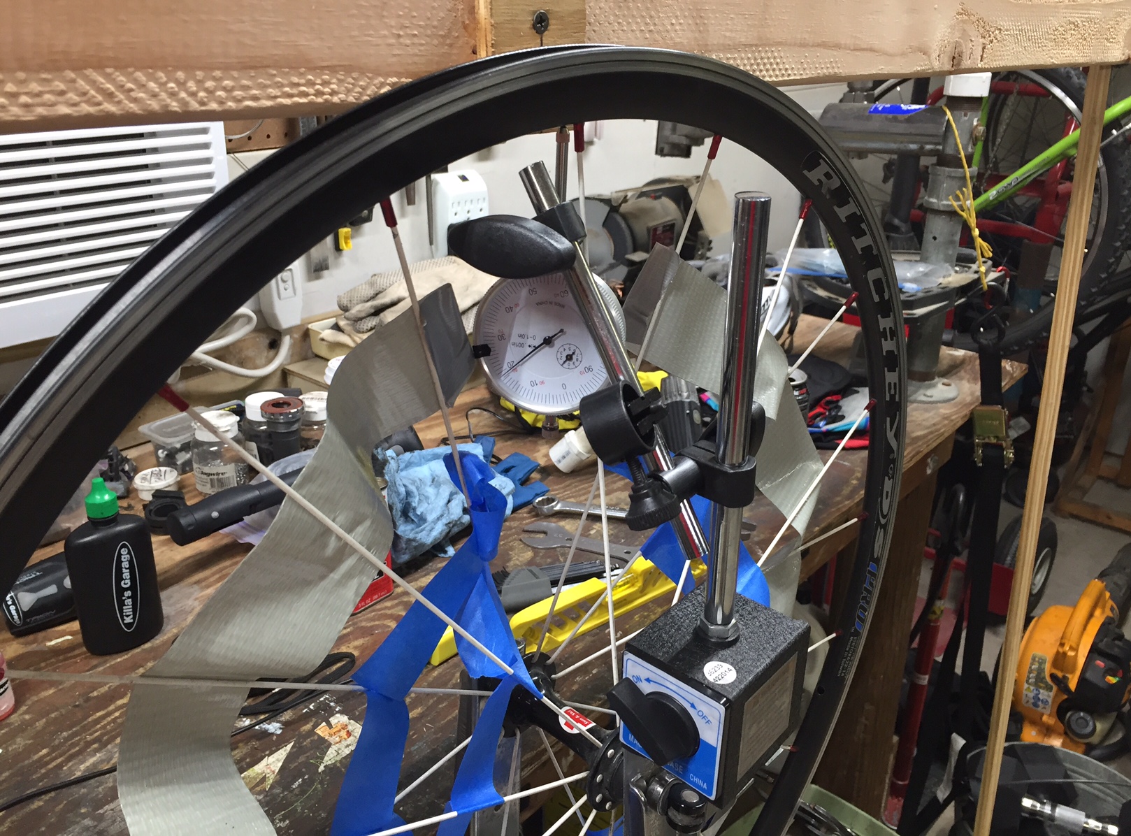
I hope to illustrate that even under severe load conditions, vertical wheel flex is measured in thousandths of an inch. And I will use spoke tension to try to prove my point. This is why I was trying to calibrate my Park TM-1 Spoke Tension Meter when I got off track in my last post.

When you apply tension to a spoke it stretches – a very small amount. The more tension you apply, the more the spoke stretches. In textbooks the tension is called stress and the stretch is called strain. The relationship between stress and strain is called the modulus of elasticity, or Young’s Modulus. Young’s Modulus for steel is ~29 million pounds/inch squared, provided you do not exceed the elastic limit.

All the spokes in a bicycle wheel are under tension. In a perfect front wheel all the spokes are under an identical amount of tension. In a perfect rear wheel all the left side spokes are under an identical amount of tension, and all the right side spokes are under a different identical amount of tension (except for some wheels laced in strange crow’s foot patterns or something.)

I’ll consider a radially laced front wheel for the rest of this post, because the geometry is easier to draw, but it won’t change my conclusions much. I will also assume the spokes are in a plane with the wheel, which they obviously aren’t. They angle out to the left or right, but this makes less than a 2% difference.

What I hope to do is use the amount of tension on an unloaded wheel and on a highly stressed wheel to show that the rim and hub stay at the same distance from each other within thousandths of an inch.

Back to my stressed spoke. A well tensioned steel spoke would be under a tension of about 200 lbs force, more or less. We can calculate the stress by knowing the cross-section of the spoke, and then calculate the strain by knowing the length. A 2mm round spoke tensioned to 200 lbs would be under a stress of ~41,000 lbs/inch squared. A 280mm (11″) long spoke undergoing this stress of 41,000 lbs/inch squared will lengthen (strain) about 0.016″. If we release all the tension in this spoke, it will shorten back to its original length.

Picture each spoke as a very stiff spring connecting the rim to the hub. In an earlier post I defined spring rate and its inverse, compliance, in relation to a tire. I calculated that a tire has a compliance of about 0.0025 inches per pound. If we make the same calculation for the spoke above we arrive at a compliance of 0.00000038 inches per pound. This is about 6500 times stiffer or less compliant than a tire.

Picture1

Here comes the trick – I am only concerned with the spoke that is pointing straight down at any time. It doesn’t matter what all the other spokes are doing. Yes, all the other spokes are responding to the applied forces, but their tension changes do not affect this analysis. By knowing the change in length of the downward pointing spoke, we know the change in distance between the hub and the rim.

If you hit a bump that pushes the rim toward the hub hard enough to completely relax the downward pointing spoke (And it takes a really, really nasty bump to do that. It will never happen in normal riding.) the rim will have moved relative to the hub 0.016″ (The thickness of three to four sheets of paper). Meanwhile the tire has compressed about a half inch! So don’t worry about vertical stiffness of your rims. They are plenty stiff enough.

Quick aside: Have you ever heard a loud snapping or cracking sound when you hit a sharp pothole or railroad track? It sounds like a spoke popped or the rim broke, but inspection reveals no damage. That is the sound of a spoke that has gone slack, snapping back into tension.

Why do we think we can feel that some rims are stiffer, some more comfortable, or more lively, or whatever? Maybe it is as Jobst Brandt described it over thirty years ago in his book The Bicycle Wheel:

“Stiffness, in its various forms, is a subject often discussed by bicyclists with a regard to components as well as frames. Stiff wheels are often mentioned with approval. However, it should be noted that a bicycle wheel is so rigid that its elasticity is not discernible because the tires, handlebar, stem, frame and saddle have a much greater combined elasticity. Therefore, the differences between well constructed wheels are imperceptible to a rider. The “liveliness” attributed to “stiff” wheels is an acoustic phenomenon caused largely by lightweight tires at high pressure and tight spokes with a high resonant frequency. This mechanical resonance can be heard, and possibly felt in the handlebars, but it is not related to the wheel stiffness.”

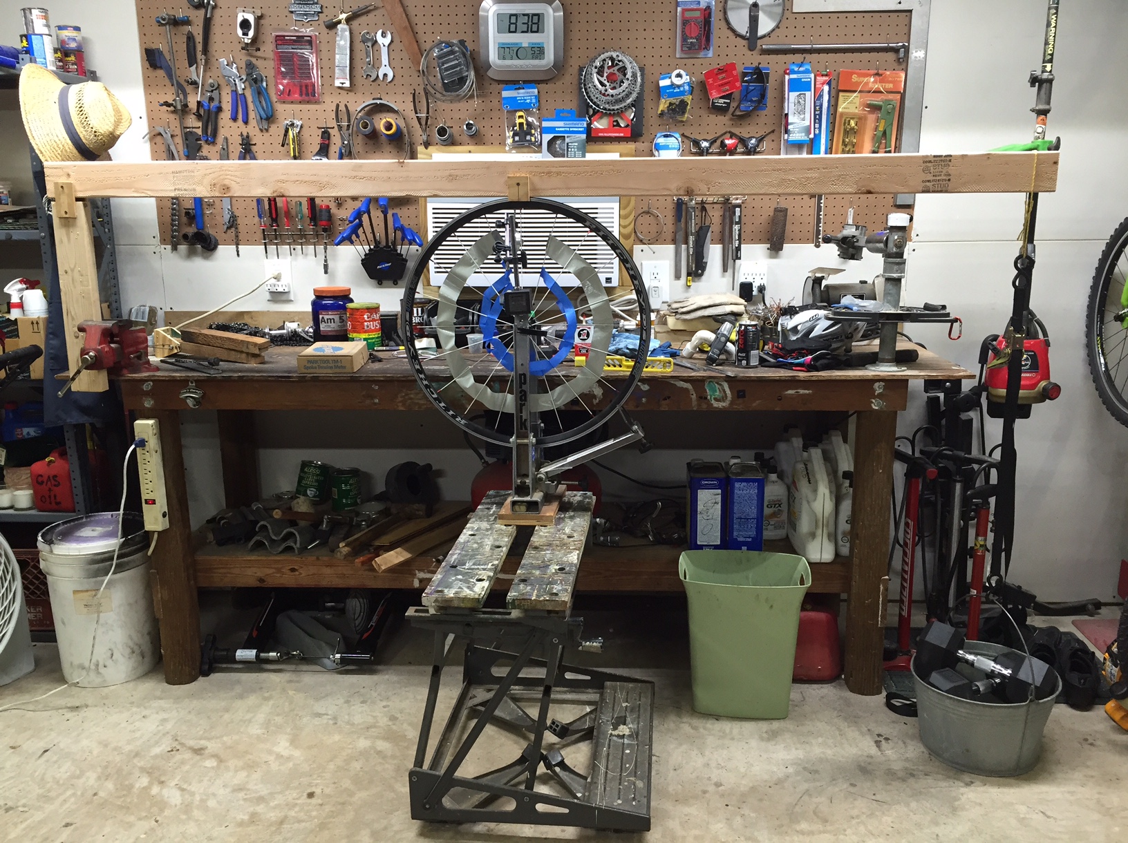
Now I ‘m heading out to the garage to take some tension measurements in support of the above. I plan to use resonant frequency to measure spoke tension, as recommended by my good friend Candyman. Wish me luck.

Killa