SRAM eTap Battery Broken Tab Repair:

ETAPBeforeAndAfter

I love my SRAM eTap wireless electronic derailleurs! I installed my first set on my old Tarmac over two years ago and liked it so much I installed a second set on my Thesis gravel bike. The other day the tab broke off one of my eTap batteries. An informal poll of my riding buddies identified three other eTap users in possession of batteries with broken tabs. These batteries aren’t cheap, and I am, so I began plotting a repair. Searching on the internet led me to lots of lamenting, one guy who fabricated a multi-layer carbon fiber tab (Really?), and one guy who attached an appropriately shaped strip of brass to his battery with double-sided tape.

Commentary on the internet suggested that SRAM would replace broken batteries under warranty, sometimes immediately, sometimes with a wait, and sometimes subject to the user’s relationship with their local bike shop. And if you bought it off the internet, walking into your LBS and asking for a warranty replacement seems kinda cheesy. Besides, I don’t want a new battery that might suffer the same fate. I want something better, and I don’t know if SRAM identified a specific problem with a batch of batteries or something.

I liked the guy’s brass strip idea but I felt his design could use some improvement, so I did.

Here is my broken battery after filing away a channel to accommodate the ~0.5mm thick brass strip. The battery case is plenty thick enough to accommodate the material removal.

EtapBatteryOne


Here is my brass strip ready to be super-glued in place after a test-fit on both derailleurs to ensure correct location of the tab.

EtapBattery2


And finally, super-glued, with a few strips of Gorilla tape just in case, because as my friend Dougie says about backups – “Two is one and one is none.”

EtapBattery3

I thought everything was good to go. I tested my repair in both derailleurs. It fit great. Then I tried to put it in the charger and it wouldn’t snap in! It turns out my tab was a bit too long. I filed it down and now everything is good.

In case you care, my repair resulted in a 2.4 gram weight increase. That makes me wonder if a charged battery weighs more than a discharged battery. What do you think?

Retrofitting a Threaded Bottom Bracket in a BB30 Shell, and Bonus Hub Failure Pictures


ReadyToPress

I get requests like this from time to time: “Can you take all the components off of my old frame and put them on my new frame, and put all the components from my new frame on my old frame?”

My answer usually goes something like “Yes, but you might need a new front derailleur and the crankset might need some kind of adapter.”

The front derailleur fit question is just whether the derailleur is braze-on or clamp-on, and if clamp-on, the diameter of the seatpost. Pretty straightforward, not very esoteric. That’s all I’ll say about that.

The crank/bottom bracket interface is much more… interesting.

For some fun reading Google “Bottom Bracket Standards Frustration”.

I recently got a request from my friend Chris to swap all the components, including the cranksets, between two bikes. One was an older Trek Postal he had just purchased, and the other was a newer Kestral.

TrekPostal

Here are the crank specs for both:

Bike One: Trek Postal Bike Two: Kestral
Bottom bracket shell:

BSA English threaded

Bottom bracket shell:

BB30

Bottom bracket bearing set:

Octalink cartridge bottom bracket (The bearings were still good. Those Shimano cartridge bearing units used to last forever, so I was swapping it with the crank.)

Bottom bracket bearing set:

BB30 press-in bearings, worn out

Adapter: None Adapter:

Wheels Manufacturing BB30 to 24mm bushings

Crankset:

Shimano Octalink Ultegra triple

Crankset:

Shimano Ultegra Hollowtech, which I’m sure you know has a 24mm spindle.


Installing the crankset from Bike Two onto Bike One was no problem. I screwed in a Shimano external bearing bottom bracket. The 24mm Hollowtech crankset was then a direct fit.

Installing the crankset from Bike One onto Bike Two is where it got interesting.

If it had been a Hollowtech (24mm) spindle, I could have used the Wheels Manufacturing bushings. But no, it was Octa-link. And the Octa-Link spindle is integrated with the cartridge bearing bottom bracket. That whole cartridge assembly requires a BSA threaded interface.

As an aside, there are two Octa-Link standards, V-1 and V-2, and they are not interchangeable. You can ruin your crank if you get this wrong.

As another aside, here’s an idea for an aftermarket product – a 24mm OD spindle with Octa-Link spline interfaces at each end. Are any of you aware of such a product?

Back on topic, it turns out what I needed is an available commercial product, a sleeve that press-fits into the bore of a BB30 shell and presents a BSA threaded interface! I had seen these press-fit threaded inserts but I had never given them much thought until this job. They come in two types, plastic and aluminum. I opted for aluminum because, plastic?

SleeveBB30

I started by extracting the BB30 bearings, removing the C-rings from the BB-30 shell, and cleaning everything up. I measured the honed ID of the shell to be 41.98mm.

CleanBB30Trust me, it’s 41.98 mm

I measured the OD of my insert to be 42.00mm..

42mmsleeve

So I thought, I can press this sleeve into place with 0.02mm of interference, but I wonder if I could do something more interesting.

I did a little math/science and determined that if I reduced the sleeve temperature from 80F to zero the OD would shrink to ~41.96mm. Then I could just slide the sleeve in by hand. I tossed the sleeve in the deep freeze for a few hours and sure enough, the OD was 41.96!

FrozenSleeve

Great, but not practical without a dry room to prevent the sleeve from sweating, and moisture would prevent good bonding of the requisite Green Loctite. Oh, did I mention that assembly instructions call for application of Green Loctite prior to fitting?

So I decided to do a regular room temperature interference press-fit. I was scared to death I would put it in backwards so I marked the right side.

RightSideMarkedSelecting appropriate bushings, sleeves, and spacers for pressing

ReadyToPressReady to apply Green Loctite

There was, as expected, resistance while the left end of the sleeve passed through the right side of the BB30 shell, then free movement until both left and right ends of the sleeve engaged the BB30 shell, then resistance until final position was reached.

HalfwayThereAt this point the left OD of the sleeve has passed through the right bore of the BB30 shell, and both ODs are about to engage their respective bores.

SleeveInPlace1Final placement

After letting the Loctite cure overnight, the final test of the interference fit was torquing the left and right Octa-link endcaps into place. I applied 40 ftlbs to each with no movement of the sleeve relative to the shell. Yay!

InsertOctaLinkOcta-Link bottom bracket ready for insertion. It’s old and ugly, but it still spins like butter.

I was pretty proud of myself, and I was describing this operation to my good friend Pierre, who made two astute observations:

  1. “Did pressing the sleeve into place wipe all the Loctite off?” (Answer: I don’t know. I like to think that on the molecular level there is a really well-cured film of Loctite.)
  2. “You know, Mark, the middle of the sleeve is in axial compression.” Now that’s esoteric!

One more comment: Can this sleeve be removed? Good question. I see a lot of internet forum discussion on this topic. Removal seems to be possible with a bearing press and a short tube slightly over 42mm ID.

“I removed the sleeve from my Orbea Orca so that I could run BB30 and Wheels manufacturing adapters instead. To remove it we used a headset press (posh park one) and a round halfords chrome exhaust extension.”

“Having seen one removed at a shop with the proper tools, I was able to remove an E13 variant from a mountain bike frame a couple years ago using a Park Tool headset press and two short sections of pvc pipe of different diameters – one as a drift and the other as a sleeve. The insert came out with no issues, but it did not have any retaining fluid (gap filler) as a bonding agent.”

Or with an old cartridge bottom bracket and a hammer.

Bonus Failure Pictures:

Here’s a Campy front hub that (after many years of service) failed. The failure on one side is obvious. Closer inspection of the other side reveals a crack just beginning to propagate. Interestingly this crack is in a symmetric orientation with the larger failure.

CrackedHub

CrackingHub


CO2, Air, Latex, and Ultra HiFloat Helium Balloon Life Extender

A latex inner tube is kind of like a balloon, and air is kind of like helium, so I wonder if Ultra HiFloat helium balloon life extender will help a latex inner tube hold air longer.

In our last episode of Esoteric Observations on Bicycles and Cycling I used latex balloons to demonstrate that carbon dioxide leaks through latex faster than air, and I promised to test Ultra Hifloat (a helium balloon life extending product) to see if it could decrease the flow of CO2 through latex, as soon as Amazon delivered my Ultra HiFloat. Well, I received my HiFloat and I’ve done some tests, but first…

I stumbled across a Material Safety Data Sheet for Ultra HiFloat, which lists the ingredients as: Water, Polyvinyl Alcohol, and Dextrose Monohydrate. Considering each of these ingredients:

Polyvinyl alcohol, also known as PVOH, PVA, or PVAL, is a synthetic polymer that is soluble in water. It is effective in film forming, emulsifying, and has an adhesive quality. It has no odor and is not toxic, and is resistant to grease, oils, and solvents. It is ductile but strong, flexible, and functions as a high oxygen and aroma barrier.”

Maybe the “high oxygen and aroma barrier” property will help a latex inner tube hold CO2 or air.

Dextrose Monohydrate is apparently a glucose source used as an ingredient in intravenous feeding solutions. Maybe it’s in HiFloat to make it taste better???? Any chemists reading this?

Water is water.

…so my initial tests, as previously reported, showed that CO2 leaks through a latex balloon much much faster than air.

Balloon 7Previous test result – CO2 bleeds through a latex balloon faster than air.

A latex inner tube is kind of like a balloon and sure enough, CO2 leaks through a latex tube faster than air.

Tube FinalPrevious test result – CO2 bleeds through a latex inner tube faster than air.

With my HiFloat in hand I set about to determine if the product would slow down the loss of CO2 through Latex. I filled four balloons with CO2, two treated with HiFloat and two untreated. It took about twelve hours to determine that the answer to that question would seem to be a definite NO.

CO2HiFloatT12Four CO2-filled balloons, two treated with HiFloat, two not treated, after twelve hours.

That was all fun but I don’t even carry CO2 on my bike. I use a mini-pump because I’m never in that much of a hurry and, well, I’m cheap. So what I would really be interested in is a product that allows me to run latex tubes with air retention equivalent to butyl tubes. Here goes.

I filled four balloons with air. Two were treated with HiFloat and two were untreated.

HiFloatT0Four air-filled balloons, two treated with HiFloat, two not treated, time zero.

HiFloatFinalThe same four air-filled balloons, two treated with HiFloat, two not treated, after two weeks. The two slightly larger balloons are the treated ones.

This was all much slower than I expected. It took about two weeks to see any difference, but there is a difference. The HiFloat treated balloons remained slightly larger. Still, not very impressive.

I cut the balloons open and I was surprised to see a stretchy plastic-like film that felt and looked a lot like saran wrap coating the inner surface of the HiFloat treated balloons.

BalloonsCutOpen

SaranWrap

This is all occurring at the relatively low pressures encountered in balloons. What about at higher pressures, like in inner tubes?

I installed a Michelin latex inner tube in a 23mm tire and inflated it to 100 psi. I monitored the deflation rate over several days. Then I dismounted (demounted? unmounted?) the tire and squirted 17 grams* of HiFloat into the tube thru the valve stem. I followed this with a squirt of water to hopefully keep the valve stem from getting glued shut (which worked, BTW). I squished the product around to distribute it around the tube (it’s very viscous), remounted the tire, and  inflated it back to 100 psi and spent several more days monitoring deflation rate.

How’d I monitor deflation rate you ask? I chucked up my favorite Silca pump and stroked slowly until I heard the presta valve crack off-seat. I know, I raised the pressure in the tire a small amount each time I did this, but give me a break. It’s close enough to make the point, and I did it this way consistently.

The results of all this testing were a bit underwhelming.

HiFloatGraph

HiFloat made no difference in the first 24 hours, during which time the tire deflated to ~75 psi with or without. After 24 hours, below 75 psi, the HiFloat treated tire did deflate more slowly. I’d want to run the test a few more times before calling this significant, but I’ve lost interest and I want to go do something else.

Maybe this would be helpful in a gravel situation, although tubeless is probably a better solution for that. In conclusion, I’m not sure how to use what I’ve learned. I’m not running latex tubes currently, though I have in the past, and I enjoyed what I perceived as a performance boost. I may run latex tubes in the future, but based on these results I think I’ll keep my HiFloat for helium balloons.

Next up for Esoteric Observations on Bicycles and Cycling – Installation of a retrofit threaded bottom bracket sleeve in a BB30 bottom bracket, with pictures.

Tailwinds

Killa


  • Why 17 grams? No reasaon other than that it was equal to “two pumps”, or twice the amount of HiFloat recommended to treat a large helium balloon.


Fun with Latex and Carbon Dioxide


In this post I had originally hoped to answer the question that I know has been on your mind lately:

Does CO2 leak out of a latex tube faster than air?

Tube Run OneAnd I will answer that question. But as I was surfing for information, I came across so much interesting stuff that I’m going to wander all over my topic, like I usually do.

You all know that CO2 leaks out of a butyl tire tube faster than air, right? This is why after replacing a flat on the road and inflating with CO2, if you don’t bleed the CO2 and re-inflate with air, your tire goes soft overnight. Apparently:  “The permeability of a gas through rubber depends mainly on its diffusivity and solubility in rubber. CO2 has a significantly higher solubility in rubber than O2 and N2, whereas the diffusion coefficients differ not that much. The result is that carbon dioxide passes ordinary rubber about 5 times faster than oxygen and about 15 times faster than nitrogen[1, 2].”

https://chemistry.stackexchange.com/questions/54826/why-does-co2-diffuse-through-a-butyl-rubber-membrane-more-readily-than-air

The reference [2] seems to be no longer available, and reference [1] is a cool, very old government research document from 1920 on research performed by Edwards and Pickering for development of dirigible technology. Can you say “Hindenburg”? What exactly they mean by “rubber” is not clear. They say it is made from hydrocarbons (polyprene specifically), not from trees. So I’ll assume it’s something more like butyl than latex, but it can’t be true butyl since that was apparently invented in the 1930s by scientists Sparks and Thomas at the Standard Oil Company.

BTW did you know that according to Edwards and Pickering:

“Ammonia has been considered as a filling gas for balloons. [dirigibles] Its specific gravity is only 0.596, and it offers advantages from the standpoint of freedom from fire hazard and the fact that it can be transported in the liquid form. However, the fact that rubber is quite permeable to ammonia would necessitate the use of a different type of fabric for the balloon [dirigible] envelope.”

Well, at least ammonia’s not flammable.

Where was I? Oh yes, Edwards and Pickering reported that “rubber” is about 13 times more permeable to CO2 than to air. (What they actually reported was that permeability to CO2 is 2.9 times that to hydrogen and permeability to air is 0.22 times that to hydrogen. They were fixated on hydrogen, a popular notion which changed, I’ll bet, on May 6, 1937.)

This doesn’t shed any light on the question of gas permeation through a latex inner tube. For that I want to do some experimentation. I have a few latex inner tubes, lots of air, and a supply of high pressure CO2 from the kegerator. But filling one tire with air and another with CO2 and waiting for them to bleed down is boring and won’t make for very good pictures, so I plan to use party balloons initially. They’re made of latex and their size is a good indication of the internal pressure.  I’ll fill identical balloons, some with air and some with CO2, and monitor how fast they bleed down.

While I’m at it, I’ll test a product called HiFloat, “a patented liquid solution that dries inside latex helium-filled balloons to form a coating that helps hold in the helium”. I have no idea what it is, if it works on helium as advertised, or, and this is key, if it works on CO2 or air. You see where I’m going? If it works in latex balloons, maybe it works in latex inner tubes.

…in self-quarantine waiting for Fedex to deliver my Amazon order of 20 latex balloons and one 5 oz container of HiFloat (Prime one day shipping)…

While we wait, let’s discuss the concept of filling a tire with nitrogen instead of whole air. This became popular a few years back for auto tires. The idea is that tire rubber is less permeable to nitrogen than to whole air, so your tires will maintain proper pressure longer, improving gas mileage. This is also the idea behind tire pressure monitoring systems (TPMS) on motor vehicles, though there is an argument that TPMS has led to people ignoring their tires. Whatever.

From Edwards and Pickering, rubber permeability to nitrogen is 73% of the permeability to whole air. So your tires will bleed down more slowly if filled with nitrogen. I used to think that if I keep filling my tires with air, and the oxygen keeps leaking out preferentially (nitrogen permeability = 36% of oxygen permeability), after a few refills my tires would be filled with essentially nitrogen.

Apparently that’s not entirely accurate because the bleed rate is determined by partial pressure. At some point the partial pressure of O2 in the tire equals the partial pressure of O2 in the atmosphere. At that point no more O2 gets out. By way of example, the partial pressure of O2 in the air around us is about 3 psi (20% of 14.7 psi). At a tire pressure of 73 psi (88 psi absolute) 3.5% O2 would exhibit a partial pressure of 3 psi, same as the air outside the tire. I don’t know if any of this is valid. I could be doing the math all wrong, but it’s fun to think about.

…still waiting for Amazon…

Oh, and nitrogen is dry while compressed air contains moisture from the atmosphere, and that’s supposed to be another advantage of nitrogen. There’s a lot of commercial stuff on the internet about nitrogen in tires. Here’s the most useful objective resource I could find. The guy also has a lot of other fun stuff on his site, and a cool name – MojoTireTools.com.

…balloons arrived, HiFloat is delayed for a few weeks, gonna do CO2 and air in balloons with a followup post next month on HiFloat…

Ok, I finished my testing, and wow, that was satisfying. I could almost see the CO2-filled balloons deflating before my eyes!

In the interest of scientific integrity let me state that I used a hand pump to inflate the “air” balloons, so as not to introduce moisture or excess CO2 from exhalation.

Here are pictures, initial and at one hour, three hours, and seven hours:

Balloon 0

Balloon 1

Balloon 3

Balloon 7

And here are two latex tubes, one inflated with air and one with CO2 initial and 16 hours later.
Yes, I did two runs, swapping the tubes, and observed the same result on each run.

Tube 0

Tube Final

So, yes, CO2 leaks out of a latex tube faster than air.

Well, that was fun. I can’t wait to receive my HiFloat and have another balloon party.

Tailwinds

Killa


Presta Valves are Complicated

In January of this year I wrote about Presta valves, prompted by the frequency with which people bend or break the little threaded stem on top of one. I did a little research and testing, some dissection, some math, and I prattled on for a few pages, thinking I had pretty well exhausted the topic.

The other day, sitting outside Coco Crepes eating a Bananas Foster Crepe, watching my friend “Pablo” wrestle with a slow leaking tube, I realized I had left a lot unsaid!

Pablo’s immediate problem was that when he unscrewed his Lezyne Road Drive mini-pump, the Presta valve core backed out with it, releasing all the air (and increasing the entropy of the universe a tiny amount.)

Understand, I find the Lezyne to be a great pump for high pressure tires. (Get the longest one.) And the thread-on hose works great – on non-removable valve cores. The pressure relief button is a nice feature too. Interestingly I “invented” the pressure relief button many years ago, to make it easier to pull my Silca Classic pump head (It wasn’t called Silca Classic then. It was just called Silca) off of threaded valve stems.

No alt text provided for this image

But I digress. The Lezyne thread-on hose is essential for my friend Ironman, who runs Zipp 808s on his tri-bike. An 80mm valve stem barely protrudes from the rim, making it impossible to stab with any other pump head except the Lezyne, because the Lezyne screws onto the core only. Thus the problem with removable cores. I personally have unscrewed a few valve cores with a Lezyne pump by mistake. Others have too apparently. This is one of the eight reasons for which Russell Eich advocated elimination of Presta Valves in BikeRadar.

If you do use a tube with a removable core, it might have wrench flats on the main body of the stem so you can tighten the core with a couple of cute little wrenches (spanners for my British friends) or one cute little wrench on the core and a pair of pliers on the stem body if it has no wrench flats.

No alt text provided for this image

On the left is a Zipp tube with an extender. On the right is a tube with a threaded valve stem body. These are the spares I carry on my road bike.

So what good is a removable core? It seems like a liability, not an asset. One benefit of a removable core is the ability to add a proper valve extender. By proper I mean one that screws in between the stem body and the core, and specifically not one that is just a hollow tube. But if you have the proper length stem, this isn’t an issue. As the guy on group rides that is expected to be able to fix anything, I carry two tubes and I make sure one of them is an 80mm… or a shorter stem with a proper extender. (While I was taking the pictures above, I made sure the cores were good and tight.) Oh, and I also carry a cheap “hollow tube” extender.

Brief digression on hollow tube extenders: Before you screw on a hollow tube extender, unscrew the nut on the valve stem core and tighten it against the backstop in the open position. Otherwise the extender might drag on the nut, rotating it and closing the valve stem –no air gets in the tire.

Sudden realization – this can happen when you attach a screw-on pump head! I think this is what happened when trying to pump up a tire on a recent ride. I thought my pump was malfunctioning. Forehead slap!

Moral of the story: Be careful using a Lezyne or other thread-on pump head on a removable valve core.

1. Unscrew the nut on the valve stem core and tighten it against the backstop in the open position

2. Push the head on as far as it will go before rotating it. This may prevent the O-ring from grabbing the nut and closing the valve while screwing on the head

3. Don’t tighten the pump head too much (the pressure seal is made by the o-ring; the threads don’t need to be tight)

4. Release the pressure in the hose before unscrewing it, and

5. Hope the valve core is tightly threaded into the valve body.

What About Tubeless? Valve stems for tubeless setups will always have removable cores for the addition of sealant, so be sure to tighten the core well when you put it together. Apply backup to the body of the valve stem while tightening the core so you don’t twist the stem and get your tubeless tape in a wad. This will cause a leak.

To add a layer of complexity, some tubeless valve stems have a round base, and some are rectangular. I prefer round. I think it is less disastrous if it gets twisted, based on a limited dataset of a few problems with rectangular base stems. 

No alt text provided for this image


Next decision, threaded or smooth body? I dunno, I kinda like smooth body valve stems. It’s easier to get your pump head on and off. And they don’t tear up the rubber seal on your pump as much as threaded stems. Not an issue with a thread-on pump head, as it doesn’t engage the valve body. I once ripped a stem out of a tube while wrestling a pump head off of a threaded valve stem.

If you do use a threaded valve stem, do you screw the nut on it? To me, it just slows down a roadside flat repair for no reason. I have a tray full of valve stem nuts on my workbench if you want some. Ah, but Killa, what about when the valve stem rattles inside the rim? This is a common problem on deep carbon rims. It can sound like rocks rattling around in your frame. The nut can prevent that. OK, but I prefer a piece of electrical tape with an X slit in it punched over the valve stem. Bonus tip: Use a contrasting color of tape to make spotting the valve hole easier. (See the picture in the header of this post)

 Of course threaded stems are essential for tubeless setups. My ideal tubeless valve stem is threaded on the lower half of the body and smooth on the top where the pump engages it. See the stem on the right in the picture above.

One last thought on valve stems – I thought that Presta and Schrader were the only options for bicycle usage, but in researching for this post I learned that there is also something called a Dunlop valve. Who knew?

One more last thought – And I’ve said this before. I’ll say it again. In this age of Unobtainium bikes and Upsidaisium components, why are valvestems still made of brass?

All Torqued Up

TorqueWrenchesOne

Let’s talk about torque, not the kind you generate when you pedal your bike, but the kind you use to hold your bike together. In Zen and the Art of Motorcycle Maintenance there is a scene involving a young “mechanic” stripping bolts on the protagonist’s motorcycle because he lacks “mechanic’s feel”. OK, I can relate to that, and mechanic’s feel is great. I like to think I have it. And I use it for lots of bolts and nuts on a bicycle.

But for some connectors, notably those clamping on carbon fiber, I’ll whip out a torque wrench.

I am not going to write a why and how manual on torque; that wouldn’t be esoteric, would it? Instead I’ll poke around the “nuts and bolts” of bicycle assembly.

Why do certain connectors require certain torques? One answer is so they won’t come unscrewed during use. But the more general answer is to generate tension in the connector, thereby applying a compressive load between items to be joined. If there were a convenient way to measure connector tension directly, that’s what we’d all do. But there isn’t, so we use torque as a proxy.

Actually that’s not entirely accurate. In industrial applications it’s being done by several manufacturers, with Direct Tension Indicating Bolts.

The problem with torque as a proxy for tension is that the condition of the threads affects the relationship between torque and tension. Clean vs dirty, lubricated vs dry, old vs new. Generally, torque values assume clean threads in good condition with some level of lubrication, but that still leaves a wide margin of error. That bolts aren’t snapping off or coming loose every day speaks I think to the large window of allowable torque on these things.

By the way, I generally lubricate threads before makeup… generally. I consider the use of grease or anti-seize compound as much a corrosion inhibition measure as a lubrication measure.

Component manufacturers usually include torque recommendations in their assembly instructions. Shimano especially does a great job with their online TechDocs Library.

Now, in esoteric fashion, let’s talk about torque.

I always use a torque wrench for:

  1. Shimano’s 5mm crankarm pinchbolts. This is a heavily loaded interface, and the consequence of insufficient torque is severe. 12-14 NM.
  2. Stem/handlebar and stem/steerer bolts, those 4mm bolts that must be tightened to 5 NM. Interestingly the stem/handlebar interface must be tight enough to never slip, while the stem/steerer interface is better off slipping in a crash. I use a preset “torque key”. Mine is made by Ritchey. There are several brands. Park Tools makes one. You do know not to put carbon assembly paste on your steerer tube to stem interface, right?
  3. Seatpost clamp bolt on a carbon fiber seatpost. 5 NM. Over-tighten this one and you can deform/damage/break your seatpost. Not tight enough and your seat will slide down while you ride. This is what carbon assembly paste is for.
  4. Sometimes I use a torque wrench for threaded bottom brackets and crank bolts of the 8mm and 10mm variety. I have found that “good and tight” with a full-size socket wrench or a long-handled Park shop hex key is about right for the 25 NM crank threads. I use a 15” breaker bar for 30-40 NM bottom bracket threads.

Things that irk me:

  1. I hate aluminum chainring bolts. They break. The female half is very thin-walled and loaded in tension (hoop-stress). Check with a magnet to see if yours are steel. I’ve quieted more than a few noisy bikes by replacing a broken chainring bolt.
  2. 2mm hex bolts like on Zipp wheels and most brake pad holders. OK, the bolts themselves don’t bother me, it’s the people who overtighten and round them out, or force me to round them out trying to remove them. The loads on these interfaces are very small. Be gentle. Do not overtighten. Use your fingertips, not your hands. Shop tip – jam an appropriately sized Torx head into a rounded out 2mm hex to get the bolt out, then get a new bolt.

Zipp 2mmAbove: Itsy bitsy 2mm bolt on the bearing adjustment collar of a Zipp hub.

  1. Ball-end (Bondhus) hex wrenches. I once had the task of extracting a seatpost bolt containing a broken 4mm ball-end from a Bondhus wrench. Shimano used to warn not to use a ball-end wrench to install their dear derailleurs, but I can’t seem to find the reference now. (See Bad Torque Recommendations below.)

 Bondhus

 Things I’d like to see:

More Torx bolts. I would love it if Shimano would spec Torx bolts for their Crankarm pinchbolts. Kudos to Campy who have used Torx bolts in lots of places for many years.

A good idea:

If you are riding a thru-axle bike, tighten the thru-axle bolt with the wrench you plan to carry on the road or trail. Some of the torque specs are like 10 NM and higher. You may not be able to loosen a fully torqued thru-axle with that cute little multi-tool. You can apply this same idea to the lug nuts on your car. When you get home from the tire shop, check to see if you can budge each lug nut (one at a time, please) with the lug wrench in your trunk. Better to learn this at home than out on the road.

 Bad torque recommendation IMO:

Shimano calls for 8-10 NM on their rear derailleur mounting bolt. That’s just way more than necessary. There’s just not that much load on this interface. I use about 5 NM. I once had the pleasure of working on a damaged Dura-Ace titanium derailleur mounting bolt. It was expanded in six places, corresponding to the six contact points of the hex wrench. The bolt was literally jammed inside the housing and would not pivot. I didn’t see it being assembled, so I don’t know all the details, but the deformation clearly occurred during installation. Maybe the builder used a Bondhus wrench. Like any good garage mechanic I honed down the high spots a few thousandths of an inch until the OD was in tolerance and re-assembled the derailleur.

Damaged Derailleur BoltAbove: Dura-Ace titanium rear derailleur post deformed by hex wrench during installation.

 Torque wrench calibration:

If you have at least two torque wrenches, use them against each other to calibrate them. Of course they might both be wrong, but at least they’ll be consistent. If I have a torsion bar torque wrench and a “click” type, I’ll trust the torsion bar wrench.

Calibrating Torque WrenchAbove: Testing two torque wrenches against each other.

Or you could perform a dead-weight test.

DeadWtCalTwoAbove: 20 lb load at 6” = 120 inch lbs or about 14 NM (I clamped a 10mm hex wrench in my vise and installed a 10mm socket on my torque wrench.)

 Pedals:

Pedal threads are self-tightening due to something called precession. I grease pedal threads for corrosion prevention and I torque them pretty lightly (10-15 NM?). I think what’s important is removing and re-greasing the threads every so often, at least once a year. I have gotten pedals out of cranks for people when no one else could, (remember the mnenomic “Back Off”) but I have also thrown away cranks because I could not get the pedals out.

Brake and derailleur cable pinch bolts:

These are scary. I always feel like I’m gonna twist off the actuation arm or something. What is really important is to route the wire under the pinchbolt properly. There is always a groove. And the cable is meant to lay in that groove, so it is not simply gripped between two flat plates. Take off the bolt and inspect the mounting surface to see where the groove is and route the cable accordingly. Shimano calls for 6-8 NM and that feels really high! I don’t use a torque wrench. I screw ‘em down pretty tight and give the cable a good hard tug.

Cassette lock-ring:

This is a toughie. To tighten cassette lock-rings I put my cassette tool face up in a vise and rotate the wheel by hand. The freehub body is very thin in the area of the threads, and like a chain-ring bolt, it’s under hoop stress, so I’m very gentle. I have seen a steel freehub split from hoop stress. Many freehubs are aluminum, dimensionally identical to their steel counterparts, so not nearly as strong.

Hand-tightening CassetteAbove: Tightening a cassette lock-ring by feel.

Shimano’s recommended torque is 30-50 NM! I had never measured the torque I apply, so I took a break from writing and went to the garage for a while. I tightened a lock-ring by hand with the tool in the vise as shown above, then I put the torque wrench to it. It took about 25 ftlbs (34 NM) to tighten it further, so I’m in range.

Torquing CassetteAbove: Applying 25 ftlbs torque to a cassette lockring

Now that I’ve got you worried about all the nuts and bolts on your bike I’ll just sign off without further comment.

Tailwinds

Killa


OCD Handlebar and Saddle Alignment

Reader Samuel D asked if I could write something about getting handlebars and saddles straight.

Challenge Taken!

I’ll go one further and show you how I get brake levers at the same height and equally toed in.

The analog nature of saddle and handlebar alignment has always bothered me. There is no indexing as to the correct position. It comes down to eyeballing it and getting close enough.

Brief diversion for a story: Years ago I crashed and separated my right shoulder. For a few months after that attack by a ferocious bunny rabbit, I rode with my bars intentionally canted slightly to the right, until I recovered my range of motion in my shoulder.

Back to work: My methods still all come down to eyeball. I just use techniques and tools to augment my eyeballing ability.

This isn’t about fit. Maybe you want your bar-drops pointing down a bit; maybe you like them horizontal. Maybe you prefer your saddle pointing slightly one way or another for some reason. Maybe you like your brake levers high or low. Fine, Go for it.

This is about getting:

1.      Your brake levers at the same height on the bars

2.      And parallel (or equally toed in, the way I like mine)

3.      Your handlebars perpendicular to your front wheel

4.      Your saddle parallel to your frame.

No alt text provided for this image

Brake Lever Height – Many handlebars come with index markings to assist you getting both levers at the same height. In my opinion this is just a good starting point.


My technique for getting levers at the same height is low tech but very effective. After snugging down the levers at what looks like a good position, place a straight edge on the front of the levers. In the picture I am using a dowel. The key is locating the dowel in a notch, crook, or other identifiable feature on the front of each lever. Then sight past the straight edge to the top of the bars. Move your line of sight up and down until the top of the bars is hidden by the dowel. The bar top should all disappear at the same time. Adjust one lever or the other until it does.

No alt text provided for this image


Brake Lever Toe-in – I like my brake levers toed in. I actually like them toed in a lot. I find this gives me a more natural wrist and shoulder position. People have seen my levers and asked if they got that way in a crash. No, that’s how I like ‘em. Getting equal toe-in is difficult. There are no good hard straight lines on brake levers. They’re kind of rounded all over, for obvious ergonomic reasons. I just stand over the bike, sight down on them, and try to get them even.

No alt text provided for this image

Just for fun today I laid a goniometer next to the outsides of my levers and determined that my levers are toed in 12 degrees relative to my drops, give or take a degree.


No alt text provided for this image

Handlebar Perpendicularity (that’s a fun word) Before beginning this post my method was focused on getting the stem parallel to the front wheel. Taking that idea to the next level, I have a laser level device from Home Depot that throws a line of red light. It’s meant to be used for hanging pictures, but with a little ingenuity, I got it to throw a line on the stem and the front wheel. It’s better than plain eyeball, but the stem is too short for a really accurate comparison. And a slightly crooked stem is really annoying in the middle of a long ride.

A professional mechanic once showed me his method. With the stem binder bolts loose, stand the bike on the fork and the brake levers. In this position, tighten the binder bolts. The bars will be parallel to the fork dropouts, in theory. But there are a few assumptions in the technique. Your floor must be flat, your brake levers must be at the correct height (or not mounted yet), and on some thru-axle bikes the fork dropouts are not symmetrical.

No alt text provided for this image

Anyway that demonstration did give me the idea to focus on making the bars parallel to the front axle instead of making the stem parallel to the wheel.

With the front wheel off, stab the fork over a dowel laying on the ground. For a thru-axle fork, run the dowel thru the dropouts. Then sight down from the front edge of the bars. Move your line of sight forward and backward until the dowel is just hidden, and as for lever positioning, adjust until the dowel disappears all at once.

No alt text provided for this image

A funner but I think no more accurate twist on this method is to shine a light down from above and adjust until the shadow of the front edge of the bars just eclipses the dowel.

Saddle Parallelity (parallelness?) What’s the noun for a state of existence in which two lines are parallel? I asked a mathematician friend. She said it was probably parallelism, which also happens to be a literary term… OK.

I usually sight along the top of the saddle to the stem cap nut. The stem cap nut is always on the center line of the bike, no matter where the bars are, so it’s a good reference point.

No alt text provided for this image

I dunno, maybe it’s a little to the left. What do you think?

An improvement is to lay a straightedge atop the saddle and let it extend forward. It should point to the stem cap nut. The hard part is determining the centerline of the saddle.

No alt text provided for this image

Or if you’re feeling high tech, whip out your laser lever again.

Or you could go buy a bike with an aero seatpost and hope it’s manufactured straight.

Tailwinds and Sunshine

Killa


Esoteric Observations on an Extra Large Time Trial Bike with an Internally Routed Rear Hydraulic Rim Brake Below the Bottom Bracket

If you are ever offered the opportunity to work on an extra large time trial bike with an internally routed rear hydraulic rim brake below the bottom bracket, turn around slowly and run like hell!

I’m joking; it was a great experience but it was challenging, and by the time I finished I knew I’d write a post about it.

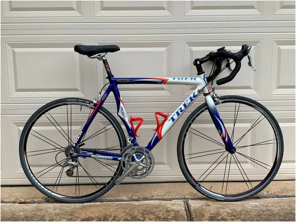
My friend (Let’s call him Flywheel), brought me his bike for some service.

This bike is a slippery speed machine. Everything is internal or shrouded. It’s quite aerodynamic. But this design is less than ideal when it comes to service and repair.

Among a few other relatively easy tweaks, the bike had a frozen rear brake. As the brake caliper was located below the bottom bracket I can’t say I was surprised. If you’ve been reading my blog you know how I feel about brakes under the bottom bracket. And Flywheel is a big guy, over six feet tall and solid, so good brakes are important for him. At least here in the Houston area we don’t have any serious downhills.

I think I’ll organize this conversation in reverse order – “A below the bottom bracket hydraulic rim brake that is internally routed on a time trial bike, size extra large”.

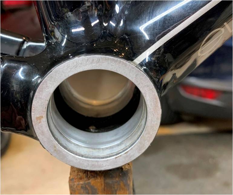
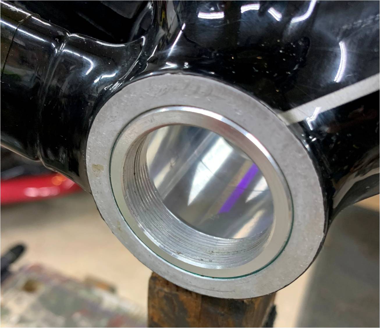
1.      Brake mounted below the bottom bracket:

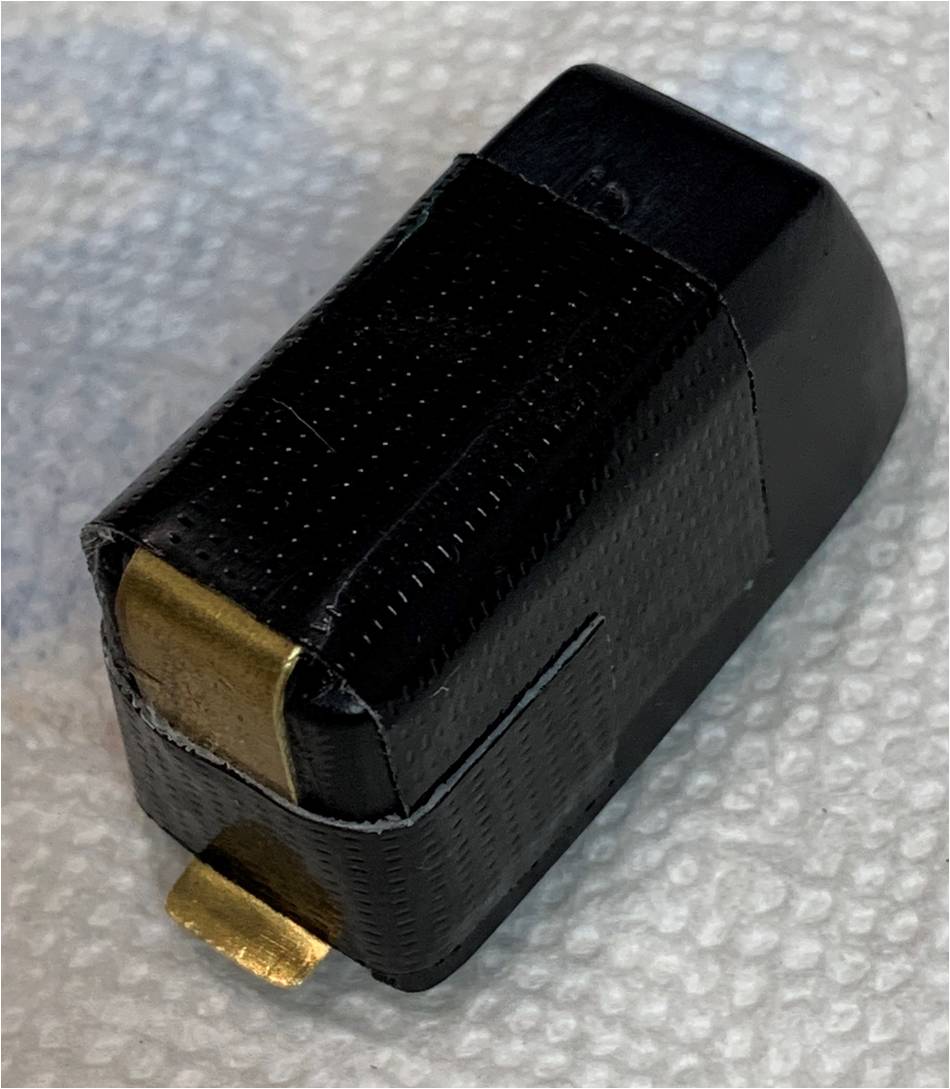
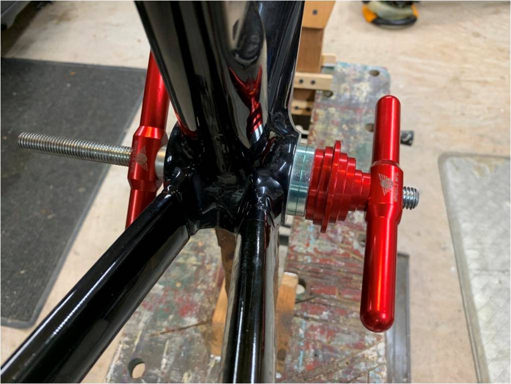
Here’s a picture taken after reconstruction, nice and clean!

This is just a bad idea! Hey, let’s put a piece of safety critical equipment under the bottom bracket – the dirtiest place on the bike.

At least on this bike there was a shroud covering the brake, though this was for aerodynamic effect and was obviously ineffective at protecting the brake from water and debris ingress.

I think this is an interface problem. The brake manufacturer makes some assumptions about the location and orientation of the caliper on the bike. For instance, on another bike I serviced, the caliper return spring is located in a pocket that effectively forms an upward-facing cup when mounted below the bottom bracket. Put that brake on the seatstays or fork and the pocket easily sheds debris and water. Below the bottom bracket it collects them! I think that if they were designing a brake for mounting below the bottom bracket, they would build it differently.

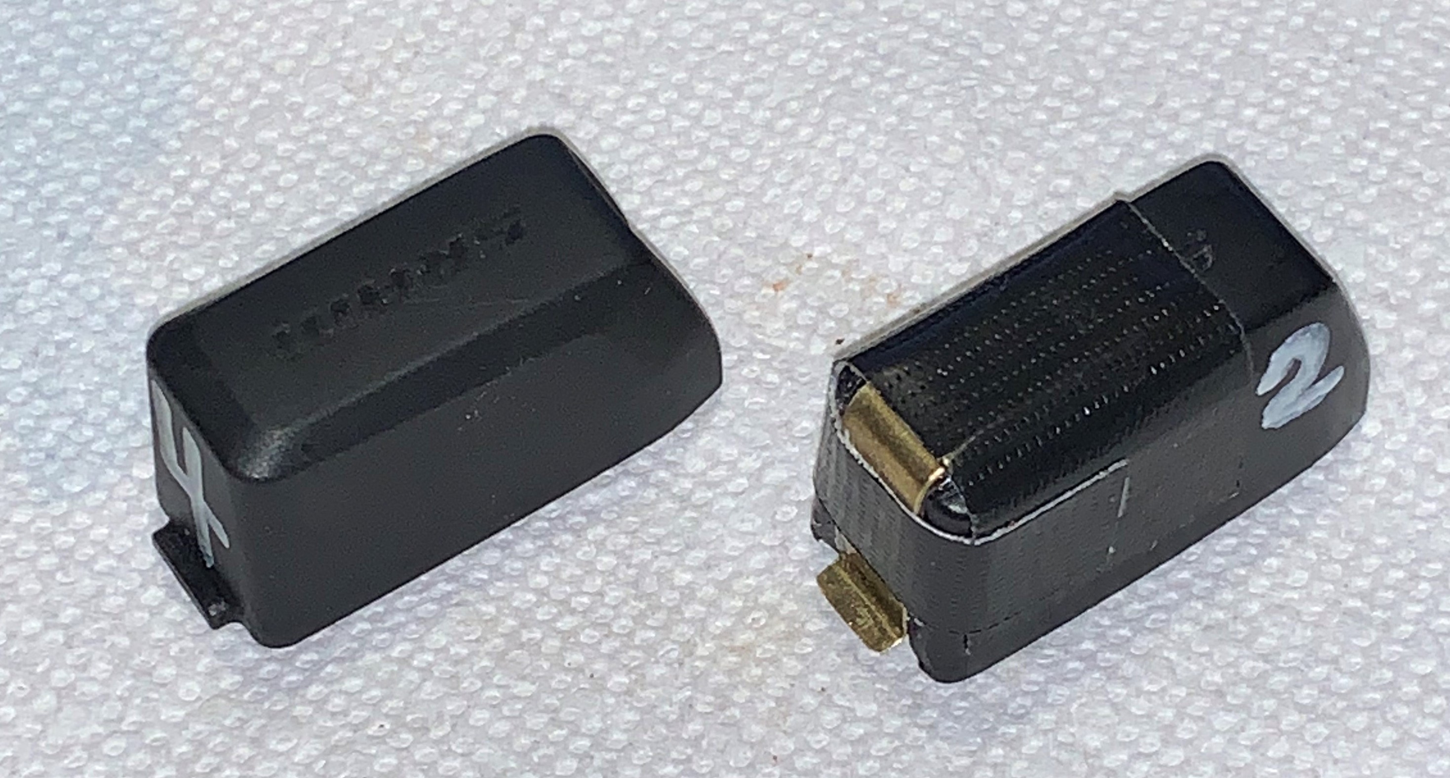
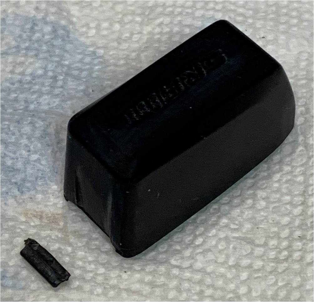
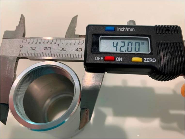
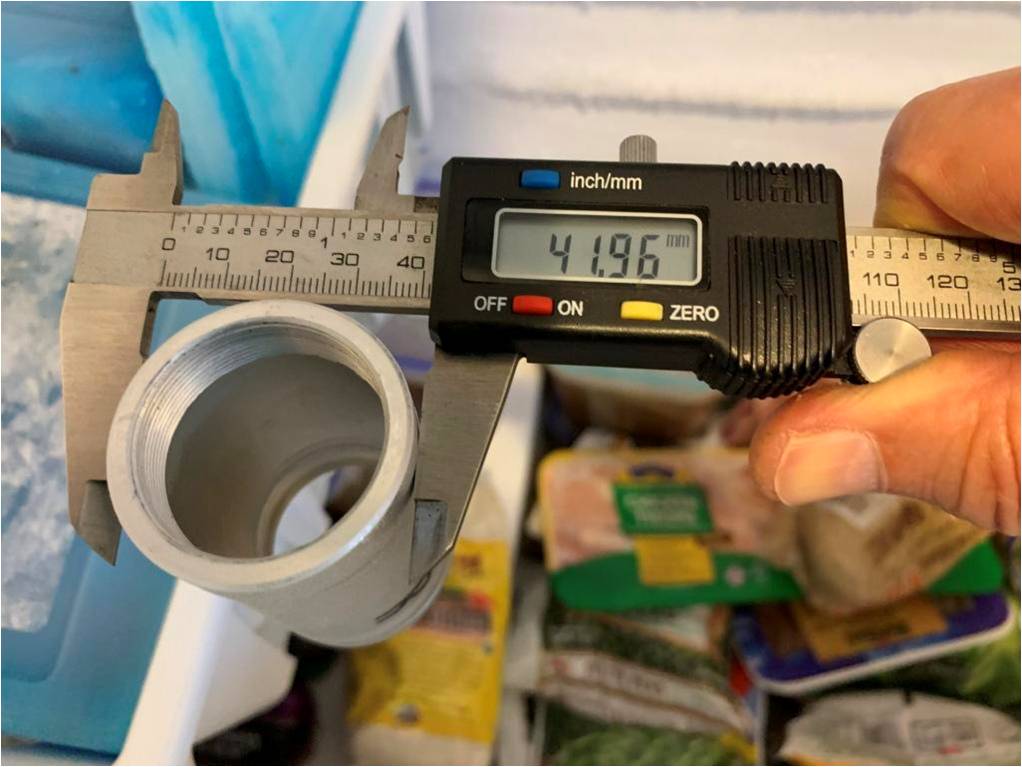
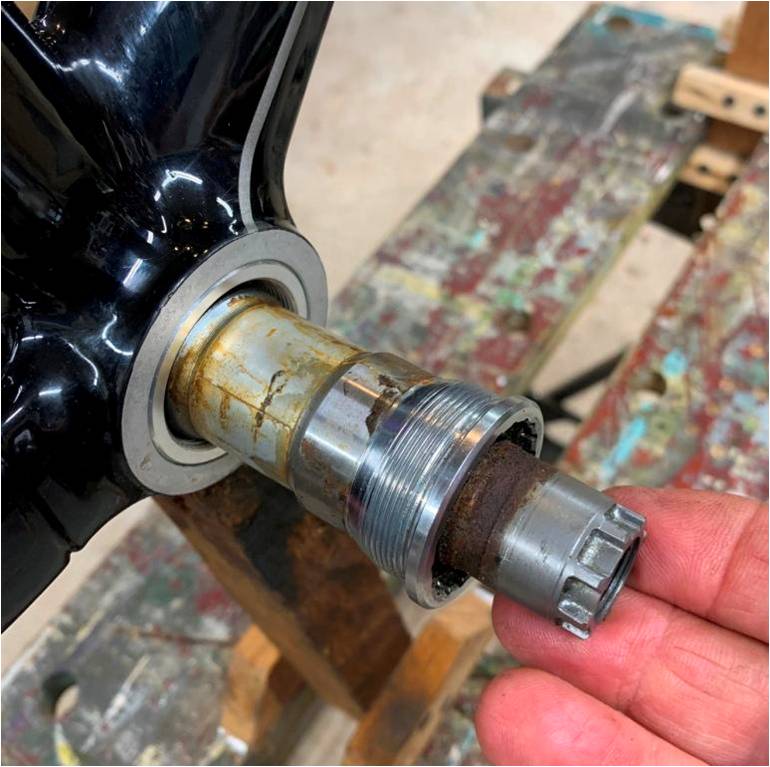
On Flywheel’s bike, there are no upward facing cups, but there are unsealed thrust bearings on the pivot studs each containing ten 1/16” balls. Upon disassembly I found forty rusty little lumps of steel.

I replaced the bearings and restored the mechanical function of the brake. What does it mean: “Do not disassemble; no user-serviceable parts inside”?

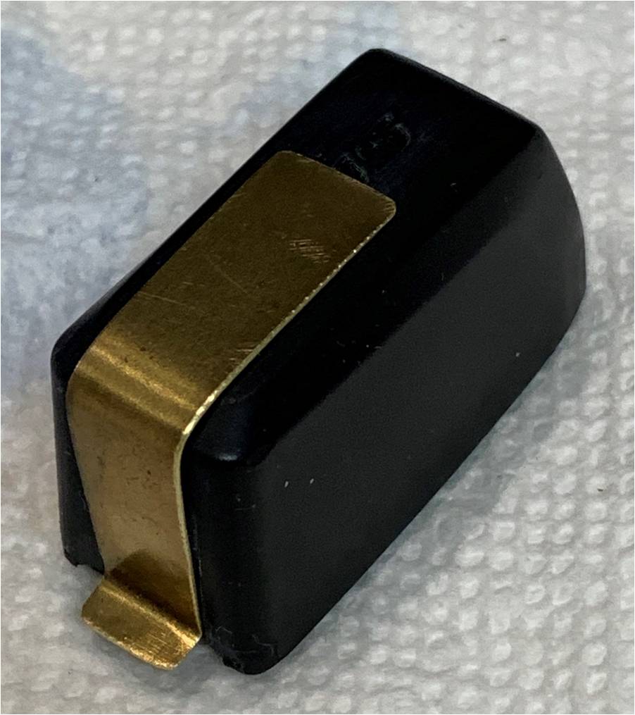
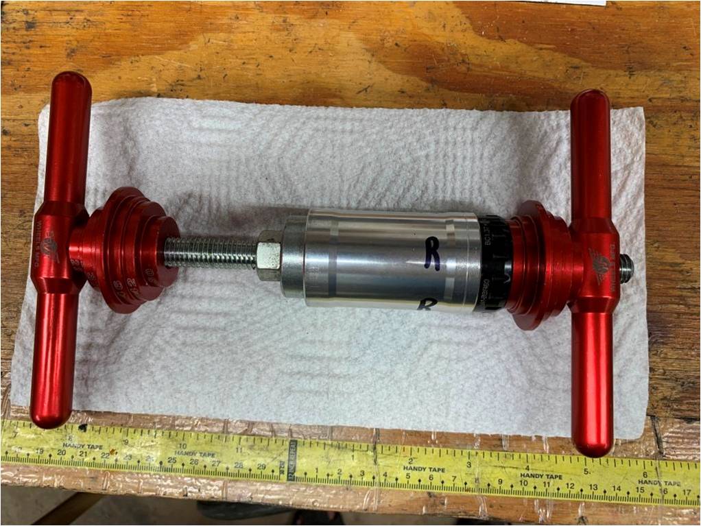
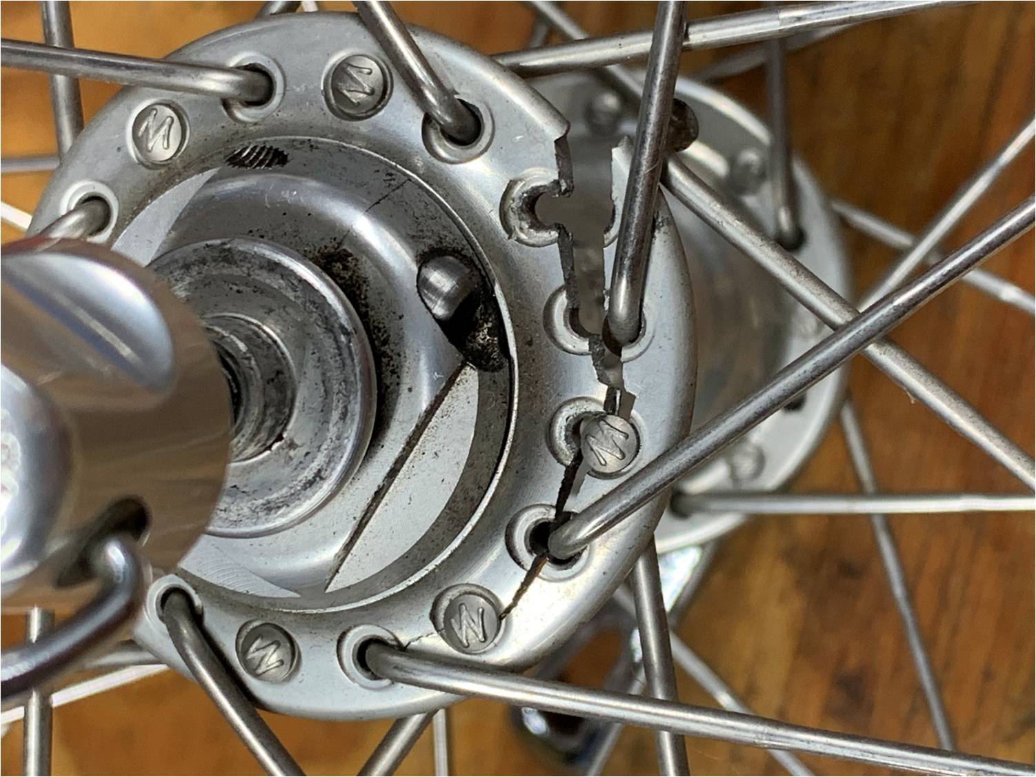
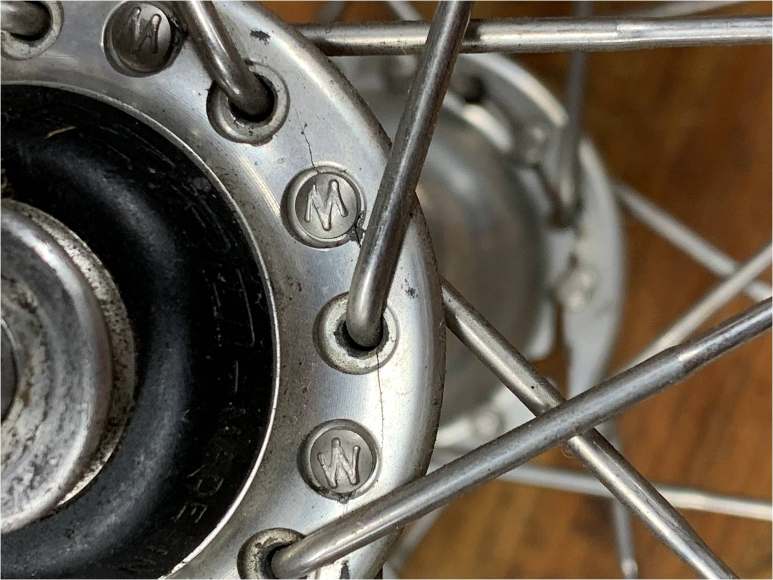
And here’s a picture of a fully functional thrust bearing of the same design from a ten year old Campy Record fork-mounted front brake. These bearings can last in the right environment.

Now you’re wondering how I came to be disassembling a Campy Record fork-mounted front brake. Well, the return spring broke, but that’s a subject for another post.

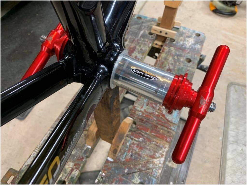
After restoring mechanical function, it was time to bleed the brakes. The hydraulic access port on the caliper faces down, of course. So flip the bike upside down to attach the syringe to the caliper, flip it back to attach the bleed syringe to the lever, bleed but watch for air bubbles which are trying to rise into the caliper because the caliper port is facing down now, flip the bike back upside down to detach the syringe at the caliper and cap the caliper port. Flip the bike upside right, detach the lever syringe and cap the lever port. This all would not be so difficult if there was any way to clamp the bike in a pivoting workstand, but there isn’t. (Is there?)

Anyway, I got the brake bled and restored hydraulic function, but that proved to be short-lived for reasons as yet unknown. I hope Flywheel lets me work on it some more.

2.      Hydraulic Rim Brakes

OK, on hydraulic rim brakes the pads are farther away from the hydraulics and therefore less likely to get fluid-contaminated. That’s about the only benefit I can name for hydraulic rim brakes.

Hydraulic disc brakes eliminate the (flexible) lever arms and cable friction. The hydraulic rim brakes on this bike do eliminate the cable friction, but they leave a rather Rube Goldberg mechanical system in place. Watch this one minute video of the brake in action.

SRAM hydraulic rim brakes at least employ a simpler, probably stiffer, mechanical system.

SRAM Red HRR brake caliper – note the adjuster barrel and release tab. It looks very much like a mechanical rim brake. You can even see the end of the return spring sticking out from behind the left arm.

Hydraulic disc brakes self-adjust for pad wear. Hydraulic rim brakes don’t.

Also, hydraulic disc brakes eliminate the need for return springs. The minute amount of piston retraction in a disc brake is courtesy of piston seal elasticity. Hydraulic rim brakes require a much larger range of motion, the same as mechanical rim brakes, so return springs are still required.

I just don’t see a compelling need for the addition of hydraulics to a rim brake system. I think fitting rim brakes with hydraulics was a step in the long range conspiracy …I mean plan… to introduce disc brakes to road cycling.

To reference an imperfect analogy, we have moved past hydraulic rim brakes the way we moved past CFL lighting. Man, wouldn’t you hate to have been the owner of a CFL factory when LED lights came out.

Anybody remember HID bicycle headlights?

3.      Internal Routing

As a mechanic, internal routing just makes everything harder, with hydraulic systems doubly so. Aside from the normal difficulties of tracing and fishing cables through a frame, doing so usually requires cutting off the “olive” terminations and fitting new ones, a much more tedious and error-prone operation than routing standard brake cables.

At least this bike, being ETAP-equipped, did not have shifter cabling all over. (There was a bit of wiring in the cockpit; blips on the bar-ends wired to a shifter unit on the stem, all internally wired of course.)

It’s a shame that all the cockpit wiring is so neatly tucked away except the last bit to the button box.

4.      Time Trial Bike

I really have nothing much against time trial bikes. I don’t own one and I don’t want one, but that’s just me. My only complaint as it relates to this post is those cute little aero brake levers with their limited travel. They never work very well, and I think there a few flaws in the design of these specific levers, but that’s beyond today’s scope. And that’s all I have to say about that.

5.      Extra Large Bike

I eventually got everything sorted, put on the wheels, and realized I couldn’t even straddle the top tube, or reach the pedals from the saddle, even with the saddle all the way down. I had to test-ride the bike standing in front of the saddle! That’s a picture I’m glad I don’t have. Hey mechanics, how do you road test a bike that is too big to ride?

Tailwinds

Killa

PS: Sorry if I sound annoyed. I’m not. Really. I enjoy this stuff. I promise not to rant so much in my next post.

How do You Even Bend the Stem On a Presta Valve?

PrestaValve

If you ride a bike, you know what a Presta valve is. If you don’t know what a Presta is, then this article may not be very interesting to you. If you do know, you still might not care. That’s why my blog is called Esoteric Observations on Bicycles and Cycling.

For a long time I have been wondering how people manage to bend or break the little stem on the end of a Presta valve. Yes, I know, it happens attaching a pump or removing it. But really, is it that delicate? Let’s find out.

I attached a string to the nut of a presta valve on an old tube and exerted a lateral force (measuring the force with my Park Tools DS-1 digital scale of course).

At about 15 lbs the stem broke off, right where you’d expect it to, at the point of highest stress, where it enters the neck of the valve body. I was surprised that it broke rather than bent, based on the number of bent stems I’ve seen over the years. It must have been harder and more brittle than average.

I’m not sure what my advice should be based on this little experiment with a sample size of one. Be more careful attaching and removing the chuck from the valve? Spend more for a premium quality chuck than you did for your pump? That’s about all I have to say about breaking off the stem, but let’s keep talking about Presta valves.

Did you ever notice how you have to get above the pressure in the tire to start air flowing? Two things are at work here, both related to the little cone-shaped rubber seal inside the valve.

First, the rubber sticks to the metal, and you have to generate enough force to push it free. Some valves are worse than others. I’ve had valves that required 140-150 psi to unseat a valve with 90 psi behind it. The solution to this is to depress the stem by hand momentarily to unstick the rubber. This does let some air out of the tire, so don’t hold the stem down long. I like to bump the stem with my chuck. I get a satisfying “pffft”, letting me know I have unstuck the rubber without letting out significant air. And no, I have never bent a stem by doing this.

Second, because of the conical shape of the seal, the diameter at the inside of the seal is larger than the diameter at the outside. The pressure in the tire is acting on a (slightly) larger area than the pressure from your pump. So it takes a higher pressure from the pump than what is in the tire to initiate flow. After the valve is unseated and air is flowing, the differential area issue goes away.

There is no spring in a presta valve. (That’s why you want to screw the nut down after inflating your tire.) Gravity, pressure differential, and air flow determine the position of the stem within the valve body. I wonder if there is a preferred valve orientation for inflation. If the stem is pointing down (stem at the top of the wheel) gravity will reseat it after each pump stroke. If the stem is pointing up (stem at the bottom of the wheel) it will fall away from the seat, and remain there until backflow pushes it into place. I wonder if this matters at all.

If your tube has a broken stem, you can still inflate the tire and go for a ride, maybe. Just be sure you place the stem at the top of the tire (pointing down) so it will fall back into place after each pump stroke, instead of falling into the tube. The other day my friend Eric (aka Bobke) described getting this wrong once. Oops.

Also, a story is told of how in 1985 during a bicycle speed record attempt John Howard’s rear tire went flat at almost 150 miles an hour. Quoting from a 1990 LA Times article:

“Three-time U.S. Olympian John Howard was mounted on the prototype bicycle that featured a double-reduction gear setup and was nearing 150 m.p.h. when the rear tire went flat … The flat tire could have killed him … There were 1,600 Gs (the measure of gravity against an accelerating object) on the valve spring of the tire.”

I was wondering if the given reasoning is a valid explanation of the world’s fastest bicycle flat tire, so I did some calculations. Feel free to check my work.

I assume this was a Schrader valve like the ones on your car tires and not a Presta, because of the mention of a spring. Stirring in some realistic numbers like 30”(?) wheel diameter and a one gram valve stem weight (I measured it), I get about 1200 Gs and a centrifugal force of about 2.5 pounds trying to offseat the stem. Fighting that force are the air pressure in the tire and the spring in the valve itself. The valve seat seal surface is about 2.8mm diameter (I measured it), so 100 psi would exert a force of about a pound, and the valve spring exerts about a ¾ lb closing force (I measured it).

One and three quarters is less than two and a half, so, yes, the valve stem could really have been forced offseat causing this flat. There may also be some things going on with the distribution of air pressure within the spinning tire. I can imagine that the pressure is higher near the outside than at the rim, but, never mind.

Two final thoughts on Presta valves:

One – in this age of wonder materials, why are inner tube valves still made of brass?

Two – the cap, use it or throw it away? I don’t use the cap, do you?

How Many Standards Do We Need for Bicycle Rear Axle Size?

126mmHub

From as far back as I can remember until the mid-1980’s, road bicycles – commonly called “ten-speeds” – were built to a de facto standard. They all looked pretty much alike. Granted there were cheap department store versions and expensive hand-built models with Italian names like Colnago and Bottecchia. But critical interface dimensions were common among bikes back then, with the exception of a few French and Italian thread selections.

Since the mid-80s cycling has existed in a state of continual innovation. In fact I’ll send half a dozen Killa’s Garage stickers to the first reader to email me the name of the bicycle manufacturer that uses the phrase “Innovate or Die” as their corporate mantra. Granted, innovation can be a really good thing. It’s the business equivalent of evolution through natural selection. But natural selection is painful. Things go extinct. I have a garage full of bicycle fossils to prove it.

I could rant about the rise of multiple bottom bracket and headset sizes in the past ten (twenty?) years, but let’s stay focused on a more recent phenomenon, the explosion of rear wheel axle options.

For eons the distance between rear dropouts (where the rear wheel fits) was 120mm. Freewheels had five cogs. Then one day somebody decided that we needed six cogs on our freewheels. Six cogs wouldn’t fit where five did. So a new standard distance between rear dropouts was introduced – 126mm.

Just like that, your 120mm bike frame and rear hub became extinct.

Somebody decided to cram seven cogs in the same 126mm space and it worked, but when they tried to fit eight, they said, we need a new wider standard – and 130mm dropout spacing was born.

Boom, your 126mm frame and rear hub went the way of the dodo!

Oh, and about that same time they switched from freewheels to cassettes/freehubs. A cassette/freehub combination does the same thing as a freewheel. It’s just a different design, and it’s not interchangeable with a freewheel.

Nine, ten and eleven cog cassettes followed, and thankfully they all fit in the same 130mm spacing, even on the same freehub (sometimes). Twelve cog cassettes are coming, and apparently they fit in the same 130mm spacing. Phwew, evolutionary convergence!

On a separate but related evolutionary path, mountain bike builders set their own standard of 135mm. The extra width was said to allow wider spoke flange spacing for greater lateral stiffness. Or maybe it was just to ensure that you couldn’t use your road hub on a mountain bike. Whatever.

So far this was evolution plodding along at a reasonable pace, 3 to 4 standards over something like 30 years. The Cambrian Explosion of rear axle evolution began about five years ago with the introduction of thru-bolt axles and the evolution shows no sign of abating.

Manufacturers began marketing disc brakes for first mountain bikes, then road bicycles, which led to the use of thru-bolt axles for reasons beyond the scope of this discussion, making obsolete the quick-release system we have used since its invention in 1930 by Tullio Campagnolo, god rest his soul.

A thru-bolt axle requires a thru-bolt compatible frame, so your bicycle frame just went extinct again. Daaah!

Thru-bolt axles were a primordial soup, so manufacturers rushed to evolve their preferred design standard. As a result, at least three different “standard” thru-bolt dropout spacings and three axle diameter choices were developed in a period of less than five years.

Rear Dropout Spacings (mm):

Quick release – 120, 126, 130, 135 (MTB), and 140 thru 160 (Tandem), all being driven to extinction by thru-bolt axle development.

 Thru-Bolt – 142, 142+*, and 148 aka Boost

Thru-Bolt Axle Diameters (mm): 12, 15, and 20

*The difference between 142 and 142+ seems to be a 2mm lateral shift in position of the right spoke flange and the cassette.

And that’s just the rear axle. One bicycle manufacturer recently decided that the front dropout spacing of 100mm that we’ve used just about forever needs to be increased to 110mm. Daaaaah!

Look out, here comes an asteroid!!!!

For a more serious discussion of bicycle rear hubs, complete with pictures that have arrows pointing to cool things, visit www.BikeGremlin.com. In fact, if it has anything to do with a bike, BikeGremlin has probably written about it.