Cable Routing – Experimental Results


I’m back from the garage with some experimental results on cable routing friction, and they are really cool!

IMG_1490
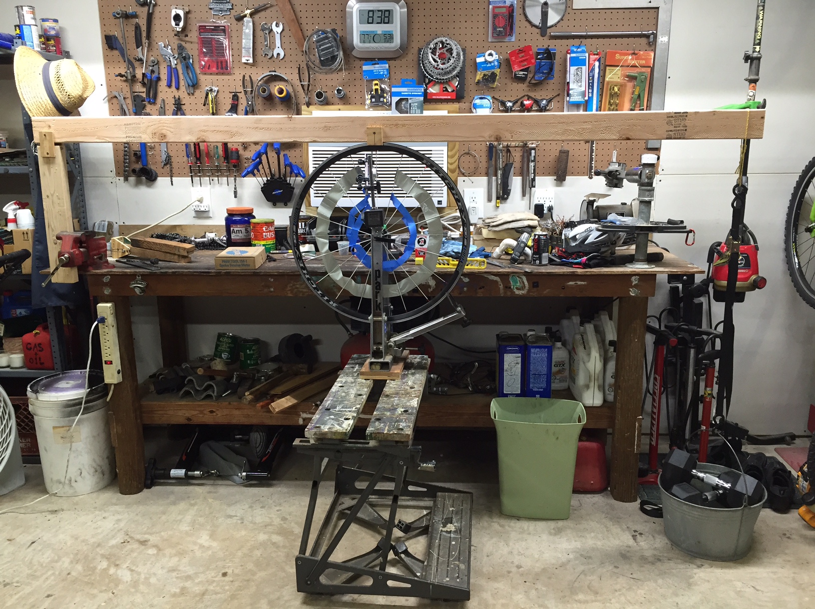
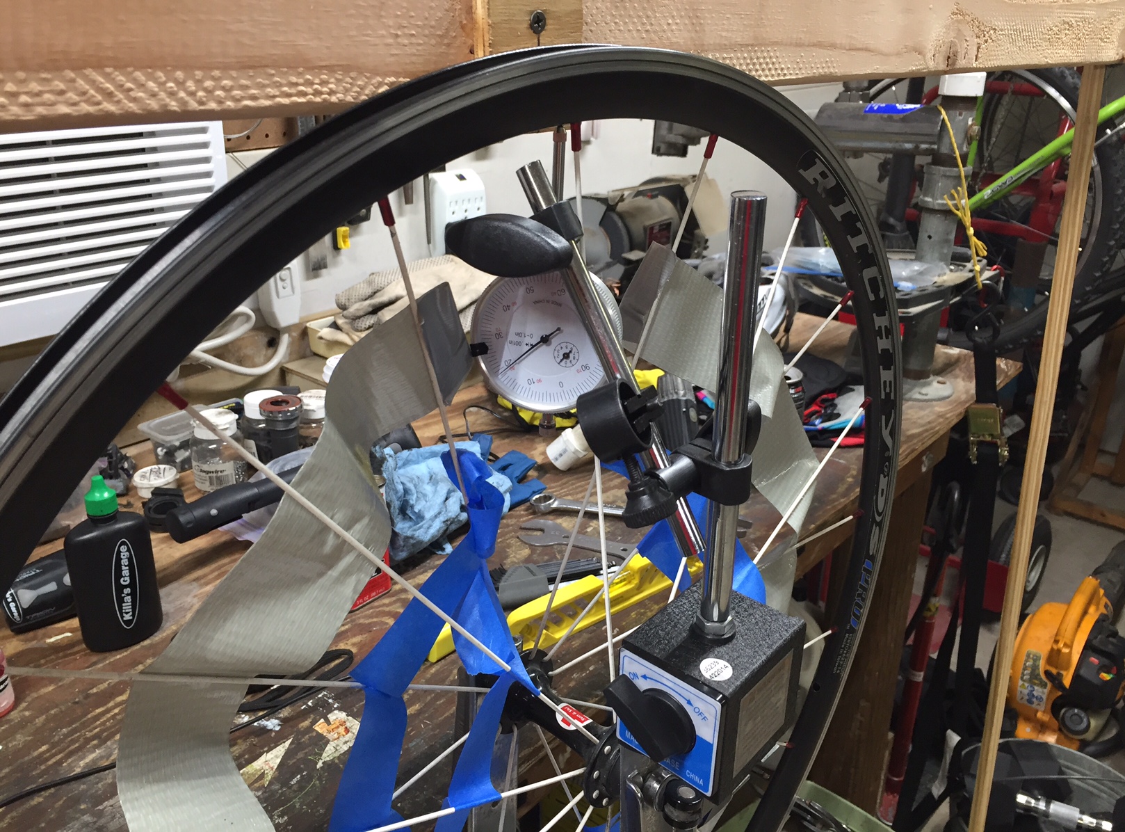
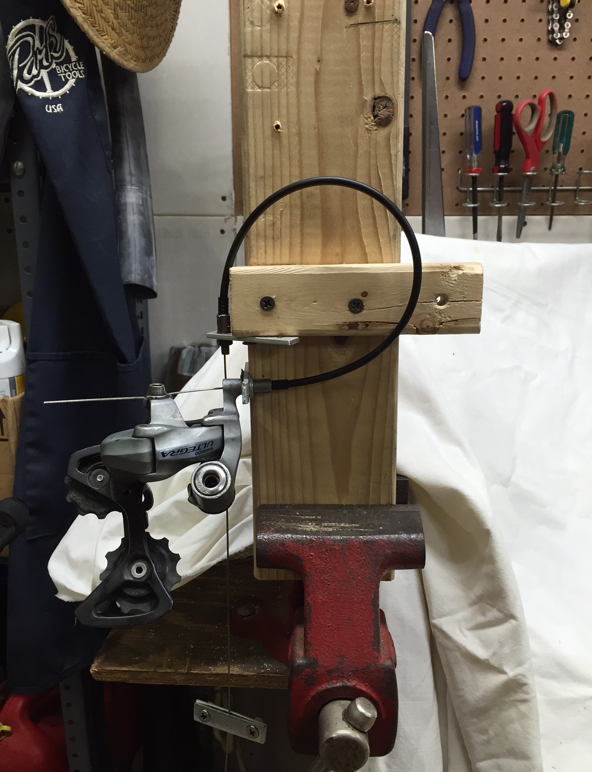
Above: Photo of my custom “Derailleur Cable Friction Tester”, loaded with a 12″ length of housing making a 180 degree turn at a radius of ~2″.

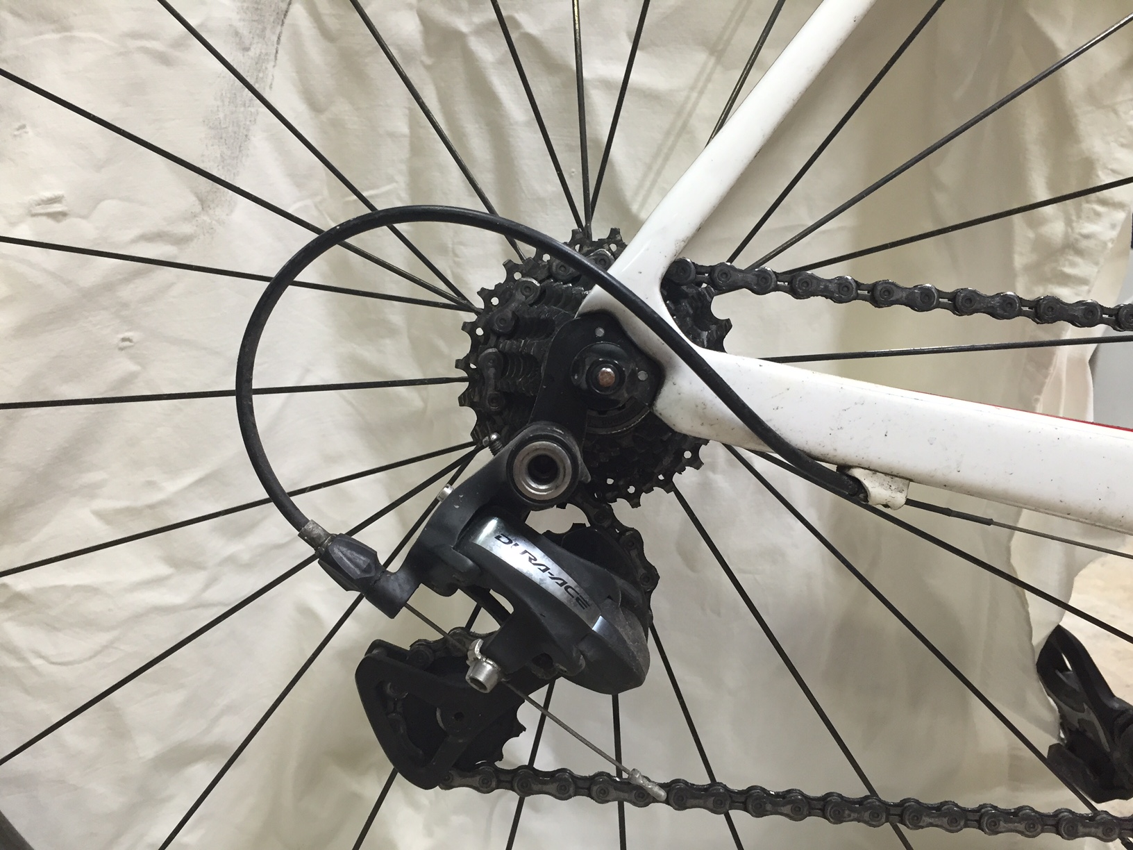
Recall from my previous post, I was wondering how best to accommodate the curve in routing the rear derailleur cable from the chainstay to the derailleur. A short tight hook, or a longer lazy curve? Historically I have preferred a long looping setup to a short tight hook. It turns out I may have been wrong.

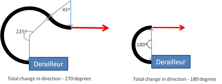
With my custom derailleur cable friction tester, I was able to measure the cable force required to overcome the derailleur spring force in a variety of configurations – total direction changes from zero to 540 degrees and turns with radii down to 1.5″ and up to 5″.

It seems this Eytelwein guy’s capstan equation is right. The radius doesn’t matter. The length doesn’t matter. The only relevant parameters are total change in direction and coefficient of friction.

Cable Friction results
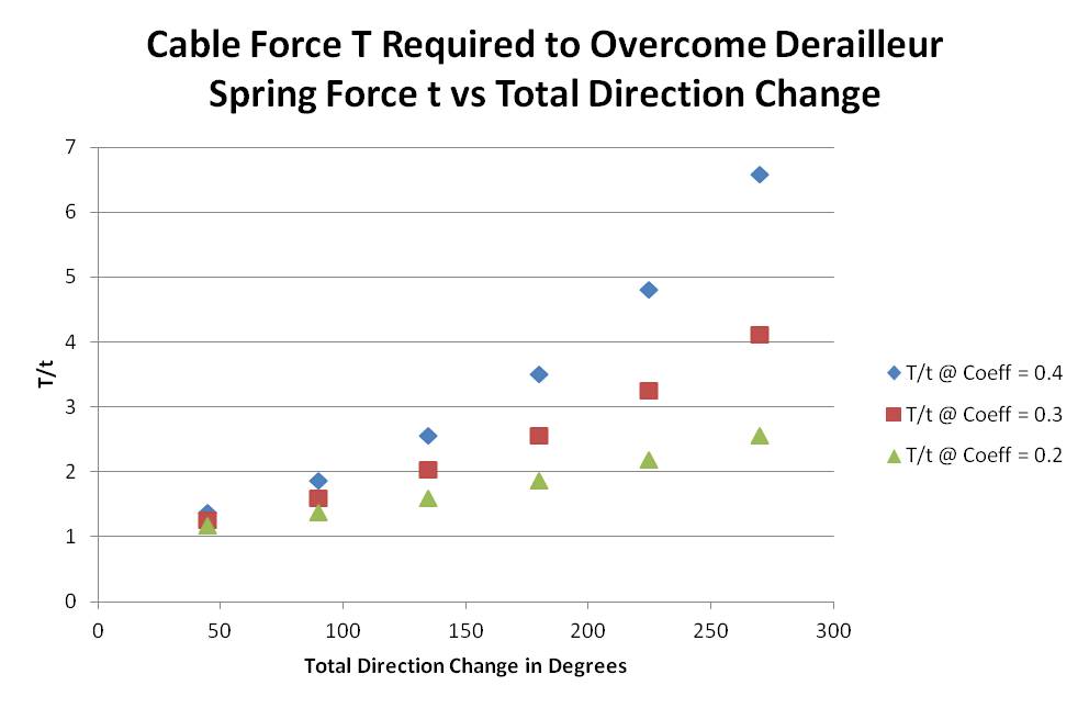
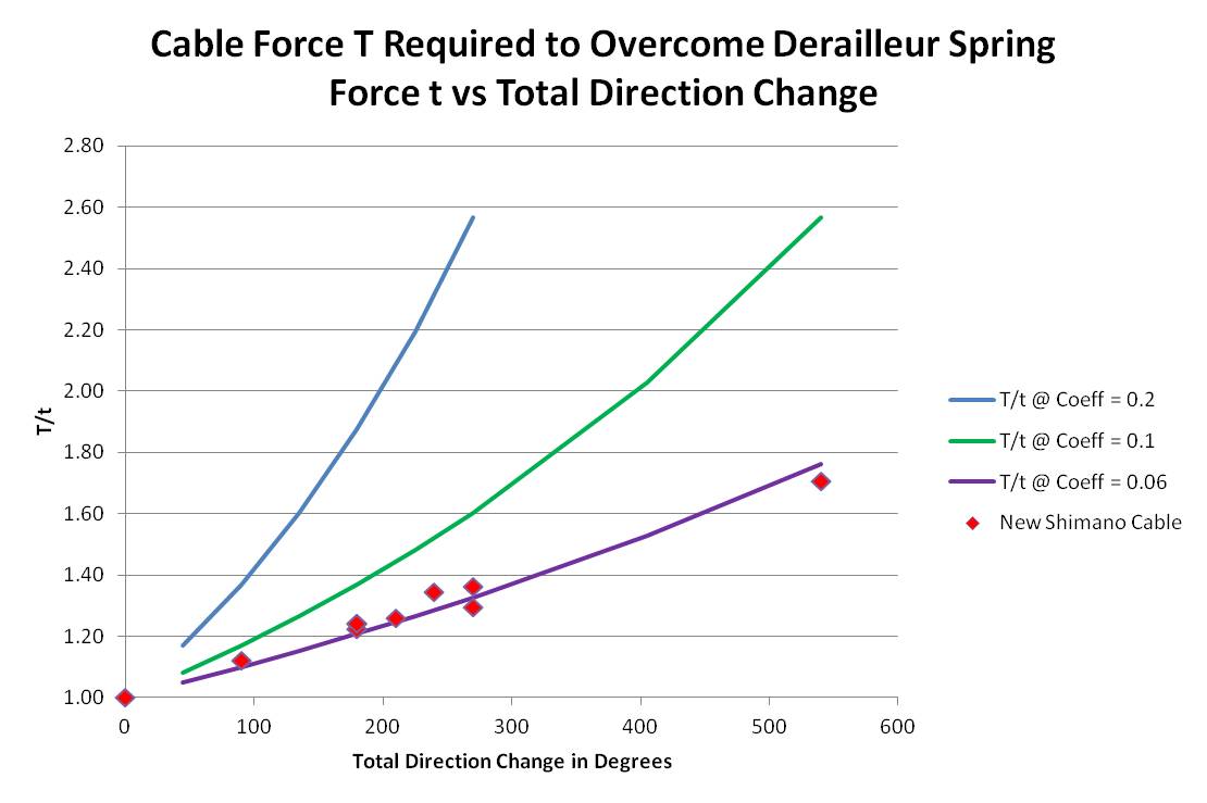
The solid lines are theoretical T/t vs total change in direction for various coefficients of friction. The red dots are my experimental results for 12″ and 24″ length housings in various configurations. To the accuracy of my measurements, which is admittedly not laboratory grade, all my data points lie on a curve corresponding to the capstan equation with a friction coefficient of 0.06.

IMG_1493IMG_1491


Above: A couple of the configurations I tested. Left: 24″ housing, 180 degrees, 5″ radius. Right: 12″ housing, 270 degrees, 2″ radius.

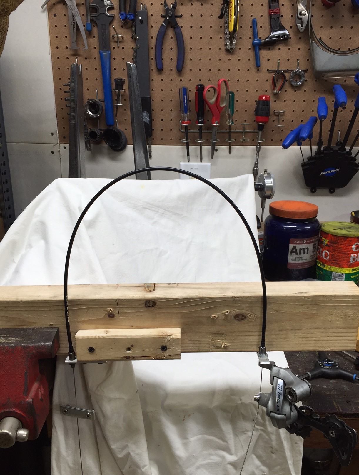
For a final test, I arranged my rig to place the cable in a configuration very much like it would be on a bike, from chainstay to derailleur.

IMG_1496

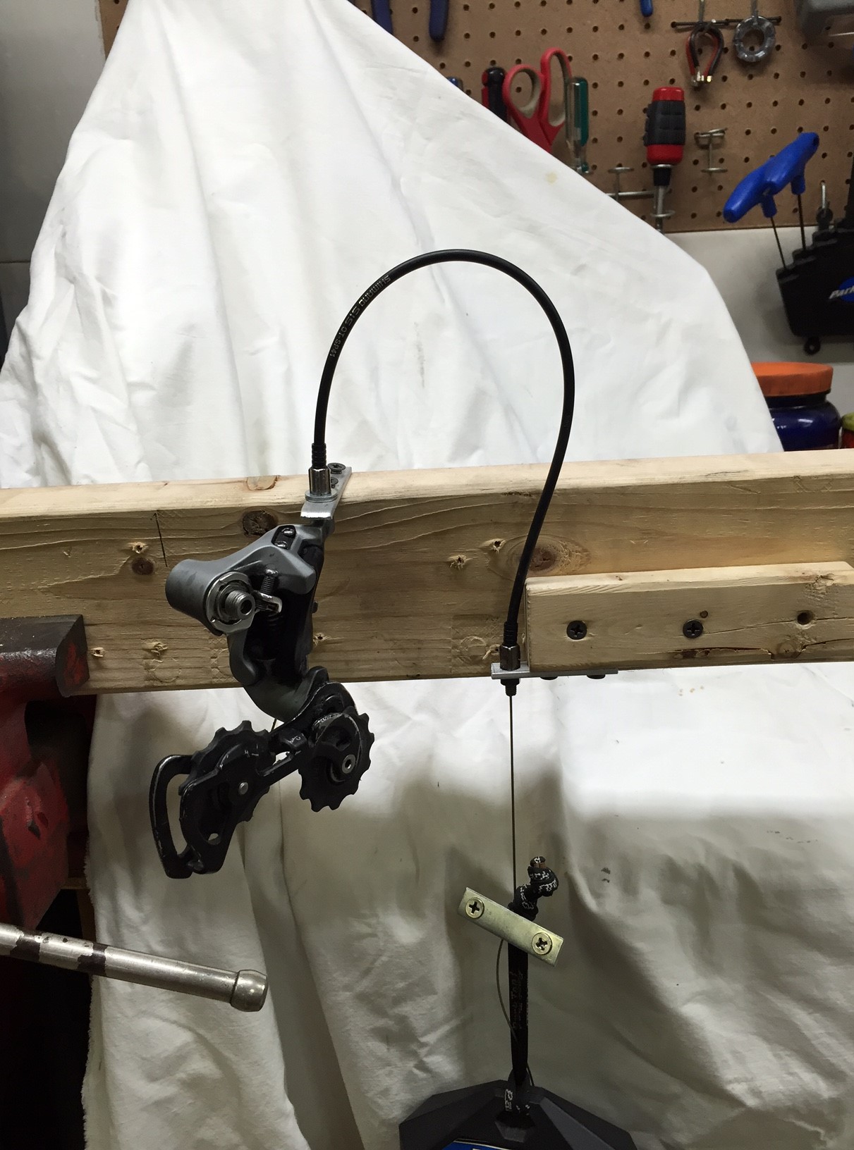
Notice how the cable housing tends to curve out before beginning the main turn-around. This results in a total direction change of greater than 180 degrees. (Call it 15 degrees out, 15 degrees back to vertical, then 180 degrees – total direction change of 210 degrees.) And sure enough, the T/t ratio falls on the curve at ~210 degrees.

Constraining the cable so that it does not go through these extra direction changes should lower the required cable force, and it does!

IMG_1498
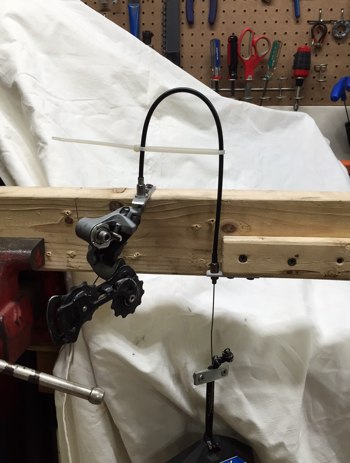
Above: 12″ cable constrained to a simple 180 degree turn at a radius of ~1.5″.

The capstan equation predicts about a 3% drop in T/t and that is almost exactly what I observed.

I repeated my test with an old cable and housing in my rig and the results were almost identical. I was surprised that the friction coefficient was no higher than a new cable and housing (0.06). But what really surprised me was that adding a drop of light oil at each end of the housing increased the required force! Solving the capstan equation for friction coefficient I got a 0.08 for both the constrained and unconstrained configurations with oil.

OK, that’s been a journey. So how can we use this information? Here are my recommendations:

  • Route cables to minimize total change in direction.
  • Try to pre-form a tight but smooth curve in the cable housing near the derailleur to minimize the bowing effect that results in greater total direction change. My friend Brian suggested that a heat gun might be useful. If I see you riding with a zip-tie on your cable to hold it in to 180 degrees, I’ll laugh at you. Use clear packing tape. 🙂
  • Don’t arbitrarily oil derailleur and brake cables. It may actually increase friction.
  • Apply this information to derailleur and brake cables all over the bike.
  • Appreciate SRAM’s recent mountain bike derailleur designs where the cable enters the derailleur more vertically than to the rear.
  • Try not to lose sleep over this, because modern bicycle cable systems work very well. These tweaks will make only a very marginal, probably not discernable, difference.

One day I might do comparative testing on different manufacturers’ cables, or on various oils and greases. I may include some static friction testing. I  may do brake cables. But for now I want to move on to other Esoteric Observations on Bicycles and Cycling.


A few closing disclaimers and comments:

  • This is all dynamic friction. What I have reported is maximum required force to stroke the derailleur by hand at a dead-slow rate.
  • As you might expect, the required force for any given configuration is not constant – or even linear – throughout the derailleur stroke. It starts out low, increases through a maximum at about mid-stroke, then declines.
  • My new cables were Shimano stainless steel cable and Shimano OT-SP41 housing. I don’t know the brand of the old cables. They came off of Trekker’s Tarmac the other night.
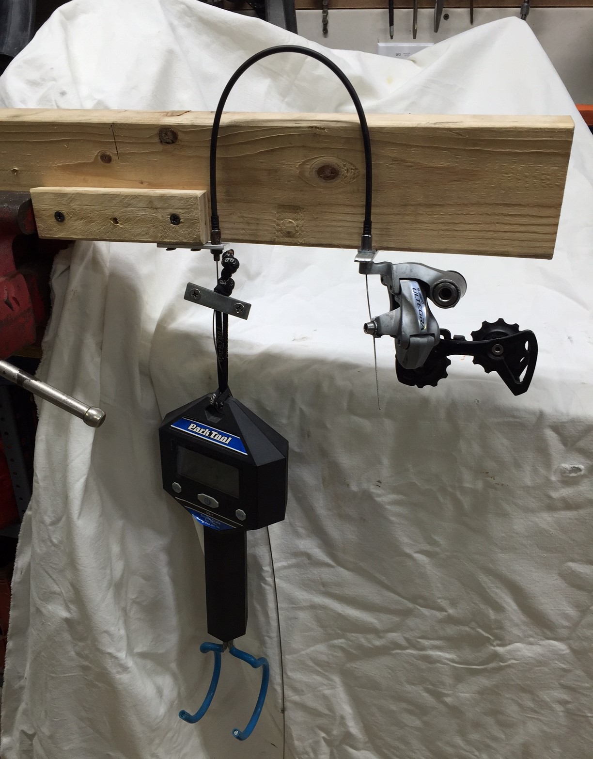
  • And if you just have to know –  it takes about 5.8 KG (12-3/4 lbs) cable tension to stroke an old Ultegra 6700 derailleur.


Cable Routing and Friction


Derailleur cable loop

You know that loop of cable that runs from the rear chainstay to the rear derailleur? Did you ever wonder whether it’s better to make a long lazy loop, or to minimize the length with a tighter curve? Yep, me too.

My scientist friend Pierre told me the length of this loop doesn’t matter. This is based on something called the capstan equation. I have no recollection at all of such a thing from my college days. I must have been absent that day. I am familiar with the idea of a capstan, usually in the context of using a small force and friction to oppose a large force.

Imagine a truck with a rope tied to the trailer hitch. You can’t hold back the truck by holding onto the rope. The truck will drag you away. Now make a wrap around a tree – no knots, just walk once around the tree with the rope – and pull on the end. You can probably hold back the truck. If not, make another wrap. Very soon you will be able to hold back the truck with a light pull on your end of the rope (or Mr. Truck will pull the tree out of the ground.) This is the capstan effect in action. In this usage, the capstan effect works in your favor.

The capstan effect works against you in bicycle cabling. On a bicycle, you are Mr. Truck, and the derailleur spring is the person at the other end of the rope, resisting your efforts to shift (or brake). The capstan equation states that the force you must apply to overcome the derailleur spring force is proportional to the total change in direction and the coefficient of friction. In fact, it is exponentially proportional to the total change in direction and the coefficient of friction.

The radius doesn’t matter. The total length doesn’t matter. Only total change in direction and coefficient of friction.

Derailleur loop compareWhich arrangement would you think requires more cable force, the long gentle loop on the left, or the shorter tighter loop on the right. Apparently the long gentle loop, according to the capstan equation.

Truth in blogging disclaimer: This simple form of the capstan equation assumes a radius of curvature large enough that the cable can be considered flexible. For a derailleur or brake wire, it’s probably good down to about a 2-3″ radius. A curve tighter than that would require a more complex analysis. Google “capstan equation for strings with rigidity” if you are interested.

Cable Friction ChartThe chart above shows the exponential increase in cable force required versus the total direction change of the cable for various friction coefficients.

This has big implications for how I will route derailleur and brake cables! I can tell you are as excited about it as I am. I’m off to the garage to do some experiments. I’ll be back in a few days with my results.


How Much Does a Bicycle Wheel Deflect Vertically? Not Much.

I’ve been in the garage taking measurements with my second generation “Killa’s Garage Vertical Wheel Deflection Measurement Device” and I now know how stiff a bicycle wheel is vertically. Let me tell you, it’s plenty stiff. A 165lb load on my test wheel deflected the rim vertically about 6 to 8 thousandths of an inch. That’s less than the thickness of two sheets of paper! That’s 165 lbs on one wheel, not two.

You can take my word for it and go ride your bike, confident in the knowledge that your wheels are plenty stiff, or read on.

I recommend you re-read my previous post on “Spoke Tension and Vertical Wheel Stiffness” to follow what I’m trying to do in this post.

I built a rig to apply a variable vertical load to a wheel in my Park TS-2 truing stand. Here’s a Youtube video of my prototype device. My second generation device is the same but with a 2×4 instead of a 2×2, to handle higher loads. Here’s a Youtube video of Gen 2.

G2 jig

Generation 2 Vertical Wheel Deflection Measurement Device

The spoke of interest in this rig is the one pointing up, because I am applying the load down on the rim, up on the axle. This is opposite the load situation on the road, but it is physically the same. Well, maybe it is wrong by about the weight of the rim and spokes – it’s close enough.

With dumbbells in a bucket, I was able to apply known loads to the wheel. My bucket of dumbbells was twice the distance from the hinge as the wheel, so my applied load at the wheel was twice the weight in the bucket (The 9 lb 2×4 applied just a 9 lb load, being centered over the wheel.)

I never thought that 42 years after taking Dr. Carver’s Statics class at LSU I’d be using what I learned to measure bicycle wheel deflection.

I used a guitar tuning app (Guitar Tuner) to measure the resonant frequency of the upward facing vertical spoke at various loads from zero to 165 lbs. I then used physics and math to convert from a change in frequency to a change in tension, and from that to a change in spoke length. If you are interested:

  • The change in tension is proportional to the square of the change in frequency. e.g., a 10% reduction in frequency equates to a 19% change in tension.
  • The change in length (strain) is directly proportional to the change in tension (stress, technically, which takes into account the cross-section of the spoke). The two are related by a constant called Young’s Modulus of Elasticity. Young’s Modulus for stainless steel is 29 million psi – it takes a lot of stress to generate an itty bitty strain.

This change in spoke length is equal to the change in distance between the rim and the hub, or the vertical deflection of the rim under load. Not quite all of the spoke relaxation is vertical because the spoke is at a ~6 degree angle from vertical. Still, over 99% of the relaxation results in vertical deflection – close enough.

Some of you are thinking, why not just measure the deflection directly? Where’s the fun in that? OK, I’ll go take some direct deflection measurements and I’ll be right back…

…I’m back. That wasn’t as difficult as I thought it would be. Dial indicators are fun. I should have bought one years ago! Direct deflection measurements are included in my results below.

Dial Gauge

Dial indicator set to read the change in distance between the rim and the hub.

Here are my results. Blue dots are the deflection as calculated from change in spoke tension. Red dots are the deflection measured directly:

Picture2

The match between calculated and measured deflection depends greatly on the value assumed for initial spoke tension. And that value is harder to determine than you’d think. I selected 150 lbs based on multiple measurements with my TM-1 tension meter and various frequency-based calculations. I could have selected a number anywhere from 135 to 180 lbs, depending on selection of assumptions.

Interestingly, if I’d have chosen 180 lbs for my initial spoke tension, the results would have overlaid almost perfectly. I was tempted to do that, but I couldn’t measure consistent tension values that high. I think this is a case of correlation with no relation.

Also, I wouldn’t try to apply a curve fit, or extrapolate beyond my measurements. My data is not that good and there’s not that much of it. But it is good enough to say that bicycle wheels deflect vertically only thousandths of an inch, and nothing compared to the flex of even the stiffest tire.

A few random closing remarks:

  • I took measurements at each load with my Park TM-1 Spoke Tension Meter, and they roughly agreed with my frequency-based results. But as the spoke relaxed I quickly got below the calibrated range of the TM-1, so my results there are not too interesting.
  • I pointed the same spoke down and applied loads. It got slightly tighter as load was applied, as expected. But it was minor, nothing compared to the relaxation experienced by the spoke directly in contact with the point of loading.
  • It was my good friend Candyman who put me onto using pitch to measure spoke tension. From there I found a trove of internet information, most notably John S. Allen’s scholarly work on the topic, published in his blog and in Human Power, Technical Journal of the IHPVA.