How Not to Install a Rim Strip

Most clincher rims require the use of some kind of tape to cover the spoke holes and stop the tube from extruding into the void there. For tubeless setups, the rim strip also seals the spoke holes against air loss, of course.
For regular tubed applications, there are lots of different rim tape products to choose from. Some of these are in the form of a thin plastic loop that you stretch over the rim and it snaps into place. Zipp, for instance, includes their own Zipp-branded loop style rim strips with their wheels.

Personally, I like old fashioned cloth adhesive tape like Velox.
Regardless of your choice, proper placement is key to proper function. The strip must be wide enough and centered so that it covers the spoke holes with some excess on each side. For most road rims this means 16 or 17 mm width. Anyway, I’m not gonna write another how-to. Here’s a link to a video. Here’s another. This is so easy that there is no narration in the first video, and the narrator in the second video pads out the run-time with some unrelated activities.

My interests are more, well, esoteric.

A few weeks back, I had a bike in the garage. I pumped up the rear tire. At about 90 psi it suddenly went flat. I took the tire off… checked the tube… found a small split on the inside of the tube about an inch from the valve stem… inspected the rim tape. Whoa!

Rimstripbad

Rim tape can fail. It can shift side to side, it can age and split. But I’ve never before seen it installed exactly wrong! The amazing thing is that this had been working for over a year!

I don’t care whether you overlap the ends or butt them, just don’t butt them in the middle of a spoke hole, OK!?

Cleaning Up a Flood-Soaked Bike

My heart goes out to those of you that got floodwaters in your homes from Hurricanes Harvey and Irma. I was lucky enough to avoid flooding at my house, though I live within a mile of devastated neighborhoods. I’ve been reluctant to post on my blog, and we’ve all been busy helping out around here, ripping out sheetrock and drying things out.

I hope you don’t need information on post-flood bicycle recovery, but I’m sure some of you do. Here are my thoughts on drying out a flood-drenched bike.

Starting from the bottom up:

Rims: Water can collect in rims even if you’ve simply ridden in the rain. It gets on the spokes and gets slung outward through the spoke holes as you ride. If floodwater got up to the spokes, it’s a good bet there’s water in your rims. Take the tires off. Take the rim strips off. Stand the wheels with the valve stem at the bottom to drain. See my post on easy tire changing.

Don’t be alarmed. I’m about to recommend WD40, a product I normally keep away from my bikes.

Pedals: Remove the pedals and re-grease the pedal/crank threads. The left side is left handed. Remember “Back-off”. Spray the pedals with WD40 or some other non-water based spray cleaner. Get it into where the springs are. Follow up with spray lithium grease. I get my spray lithium at Lowe’s in the tools area. Bearings are typically serviceable, but disassembly varies. Keep in mind some of the threads that hold pedals together are left handed. Speedplay pedals, having no moving parts except the bearings, simplify pedal maintenance greatly. Just remove the small screw on the outboard end and pump a little grease in. Personally I use cheaper Shimano pedals and replace them when they give me trouble.

Bottom bracket: Remove the crank. If you have a threaded bottom bracket, remove at least one side to allow water to drain from the frame. (On the bottom bracket, the right side is left handed, unless it’s Italian threaded.) You can pop the outer bearing seals off most bottom bracket bearings with a sharp-pointed blade to check the bearings for water intrusion. The seals will pop back on. Do I have to tell you to be careful to avoid cutting yourself doing this? Bearing Seal

Chain: This is probably a good time to change your chain, but if it’s not rusty and you want to salvage it, douse it with WD40 or your favorite chain cleaner, wipe it down, and lube it with your favorite oil.

Derailleurs: Spray them down with WD40 and wipe them off really well.

Cables: If water has gotten into your cables and stayed there for any length of time, you should just plan on changing them. If your cables are external and your cable stops are slotted, you can unhook the rear derailleur housing from the chainstay stop and slide the housing up the cable and have a look. To do this:

  1. Shift onto the largest cog.
  2. Without pedaling or rotating the wheel, shift to the smallest cog. The derailleur won’t move much, and there will be a lot of slack in the cable.
  3. Pull the housing to the back and down out of the slot.
  4. Slide the housing up the cable toward the front of the bike.

Cable One Cable Two


Headset: Drop the fork to re-grease or replace the bearings. There are lots of good videos on YouTube about headset repair and adjustment.

I have three tips to make a headset job easier:

  1. Unbolt the caliper from the fork and you can do this job without messing up your cable tension adjustment.
  2. Hang the bike from the ceiling by the rear wheel (front end down) to remove the fork. The handlebars will hang by the cables without kinking, and the fork won’t fall out when you loosen everything.Hanging Bike
  3. See my post on centering caliper brakes the right way.

Shifters: If the water was this deep, you’re probably not worrying about your bike yet. Anyway, spray WD40 into the mechanism, and follow it up with spray lithium. Shifters may not recover. There are a lot of delicate parts in there, but give it a try. Peel the hoods back and forward to wipe out as much moisture (and WD40) as possible. Oil-based products seem to degrade the rubber.

Frame: I clean my road bikes with spray furniture polish. It gives them a nice lemony scent. Matte finish paint is better cleaned with Windex Wipes, according to my friend, General Grant.

Please share any other tips you have in the comments section.


Shift Cable Fatigue Failure and Programmable Logic Controllers

My Friend Bryan is tough on shift cables. They seem to break in his shifters after about six months of use. A while back he asked me whether he should buy premium cables and hope they last longer, or buy cheap cables and plan on changing them every six months. I’ll tell you up front, I do not answer that question in this post, so if that is your only reason for reading you can stop now. I do make a recommendation, so I hope you read on.

Bryan asked me to look into fatigue resistance of shift cables. I pondered how I might build a reasonably simple fatigue test machine in my garage, and I mentioned my plight in my blog. Reader Robert W commented with the solution I needed.

“…a pendulum with a moderate mass – say 1 or 2kg. The spindle would have a groove with a radius equal to how much you wanted to bend the shift cable … A stepper motor under Arduino control could handle the power input and cycle counting…” Thanks Robert!

If you are over thirty-five you may not know what an Arduino Programmable Logic Controller is. I happen to have an Arduino project kit given me by my daughter two years ago. I never got farther than blinking a few LEDs, so this struck me as a way to explore Arduino programming, build a Rube Goldberg contraption, and advance my scientific understanding of shift cable fatigue. I think I scored a solid two out of three.

SmoothBendActionShot

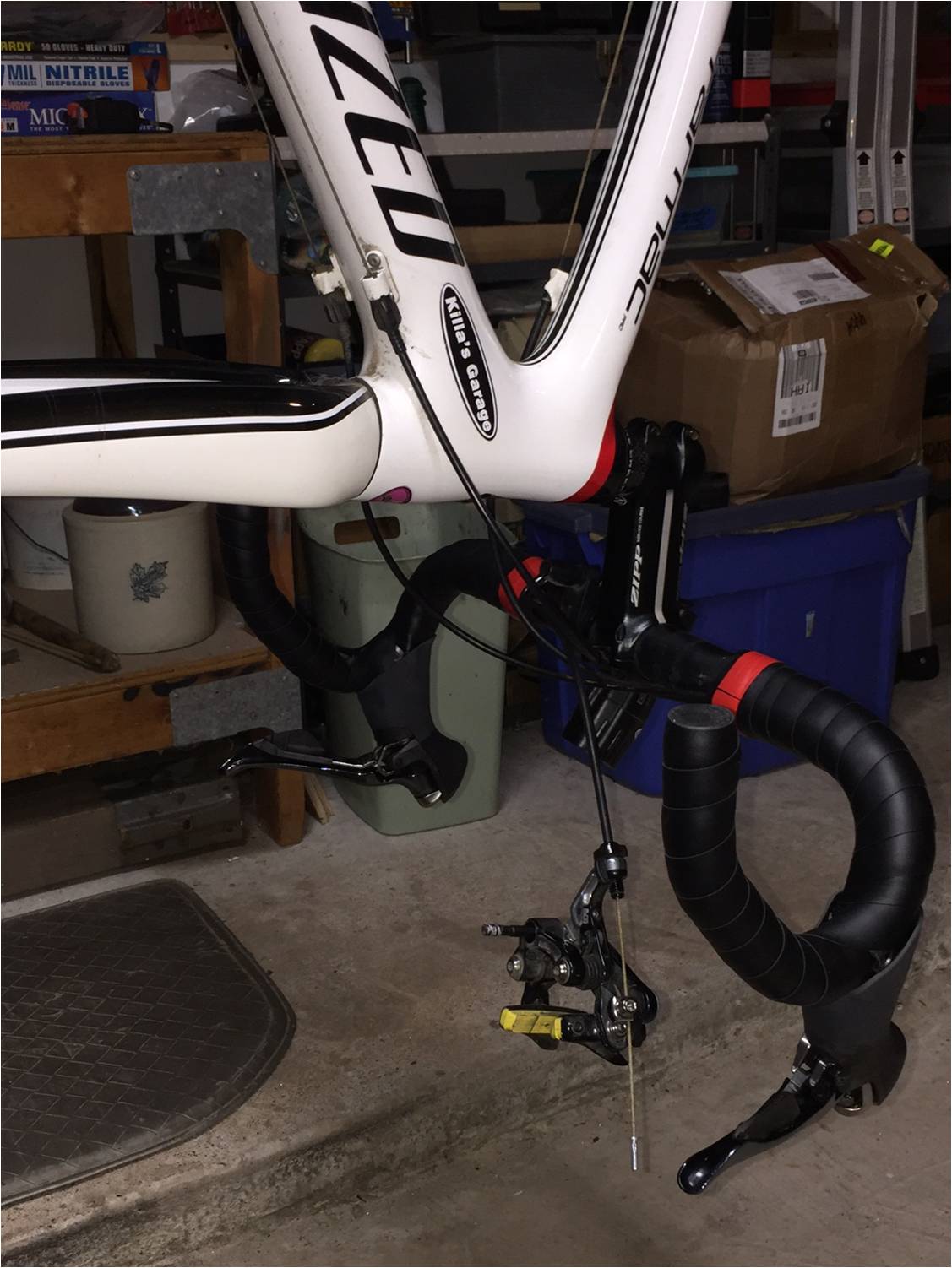
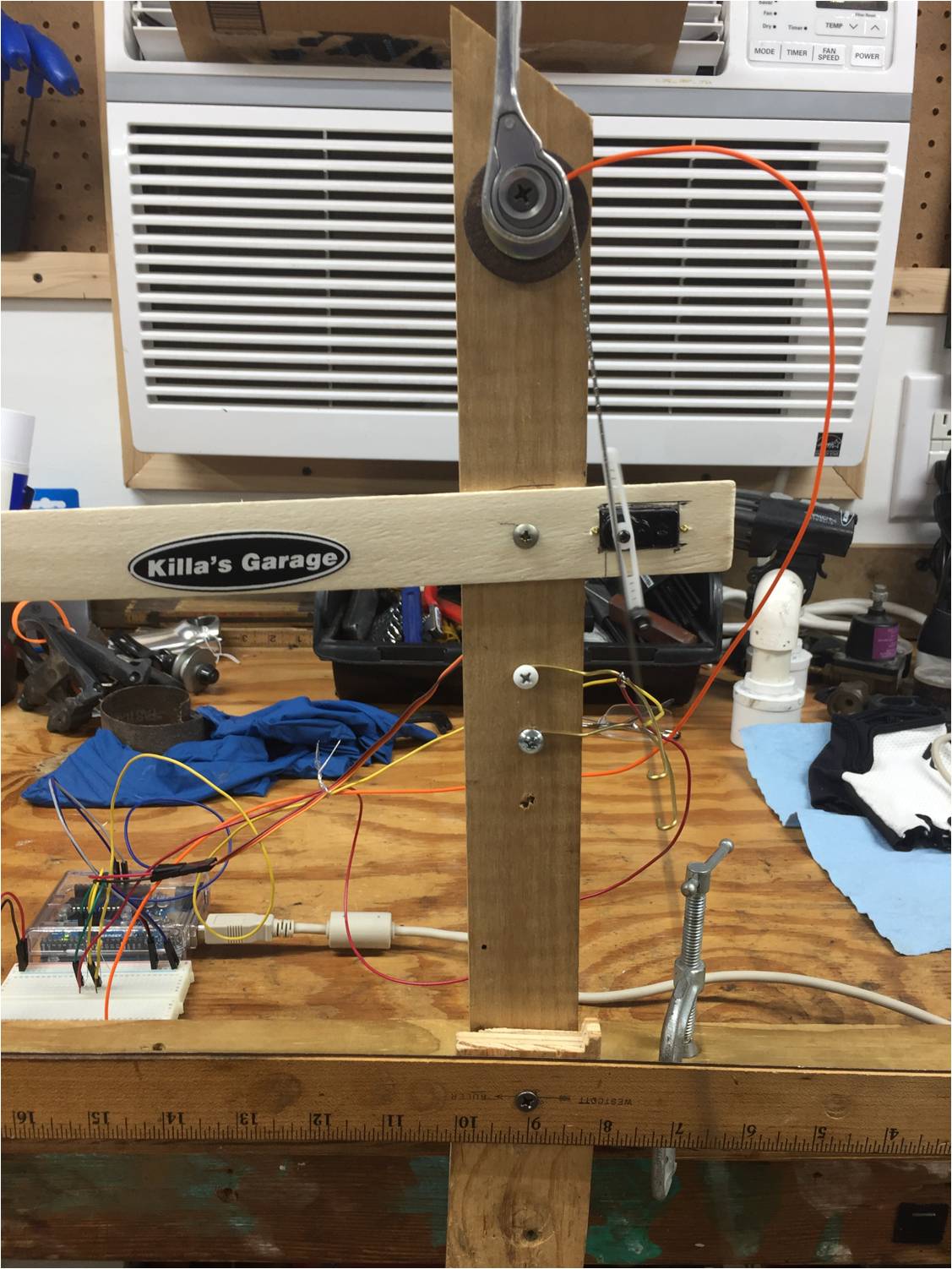
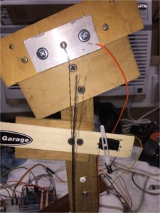
The physical rig is a nine pound weight hanging from a shift cable attached to a shifter. I start it swinging manually, then a stepper motor gives it a kick every time the cable contacts a brass wire at the right end of the arc. A second brass wire slightly farther to the right cancels the kick if necessary to control the arc. For my pendulum length, the period is about two seconds.

The last time I wrote code it was on punch cards. So it took me a while to hit my stride with the Arduino. After about forty hours of coding and debugging I had a program that would drive the servo, count cycles, and output the count to a digital display. My digital display is only four digits, so above 9,999 the display is to the nearest ten cycles, and above 99,999 to the nearest hundred cycles. In a fun bit of coding, I arranged a red LED to blink slowly indicating to add one zero to the number on the display above 9,999, and to blink fast indicating to add two zeroes to the number on the display above 99,999.

How many cycles does a shift cable go through in a lifetime? If I ride 10,000 miles a year and shift once a mile, that’s 10,000 cycles a year. 100,000 cycles would take ten years and be clearly beyond expectations. Further, different portions of the cable are flexing when shifting between different gears.

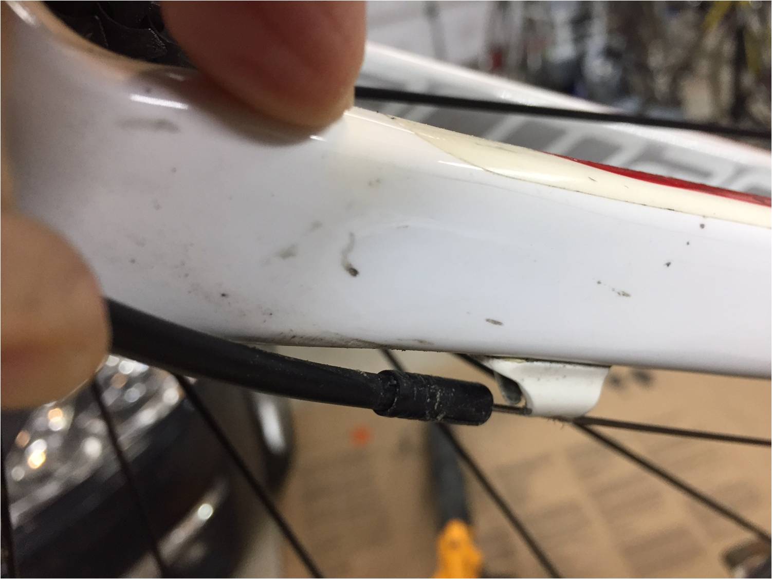
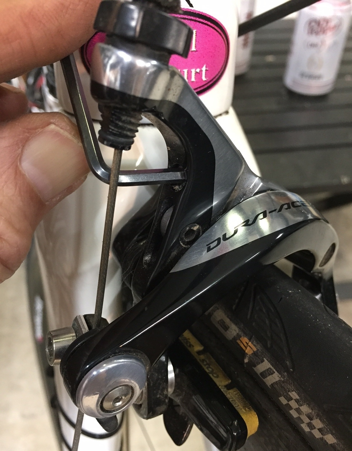
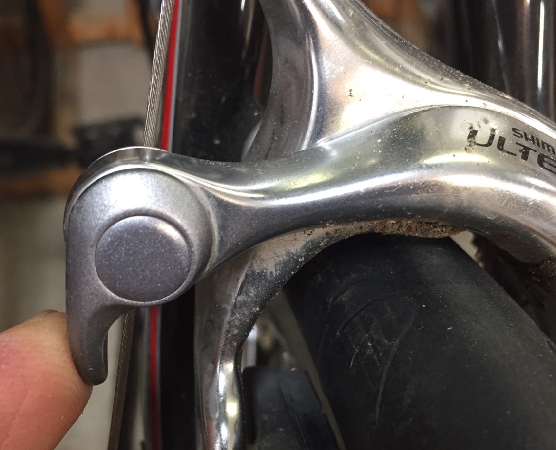
With a period of about two seconds, I get about 43,000 cycles a day. I ran my test cable thru 200,000 cycles (a little over 4-1/2 days) without failure and called it quits. The cam diameter on shifters is quite large in comparison to the cable diameter. It is large enough that fatigue from normal use should not be an issue. To put some perspective on this, go look at where your front shift cable attaches to your front derailleur. There’s a bend radius barely larger than the cable, and that is why it is so common to see broken strands near the attachment to the derailleur. That shift cables don’t break there in a few weeks of use is testament to the marvel of stranded cable.

For some interesting background on cable design see http://www.savacable.com/sava_cat.pdf.

Anyway, I had this cool fatigue test rig set up in the garage and I really wanted to break something. So I arranged a sharp bend as shown below, hung nine pounds on it, and set it to swinging. Even this arrangement lasted over 99,000 cycles!

BrokenWideShot

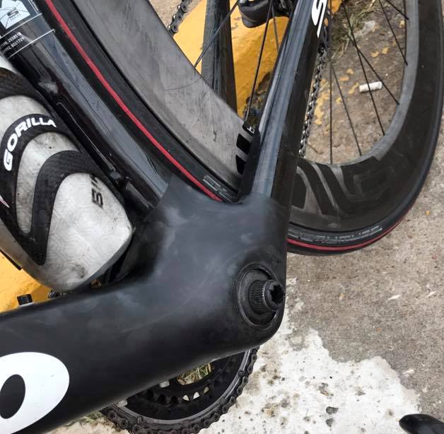
I was writing up this post two days ago and I was interrupted by a text from a friend who asked if I could help him remove a broken cable end from his Ultegra 6600 rear shifter. What a coincidence! Then yesterday another friend texted and asked me to help him remove a broken cable end from his Ultegra 6800 rear shifter! After performing surgery we checked the front shifter and found about half of the strands broken! Three broken shift cables in two days! That’s just weird.

Broken 6600
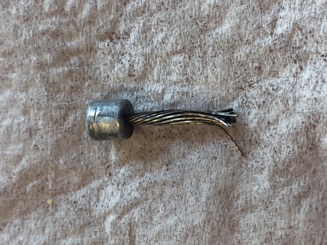
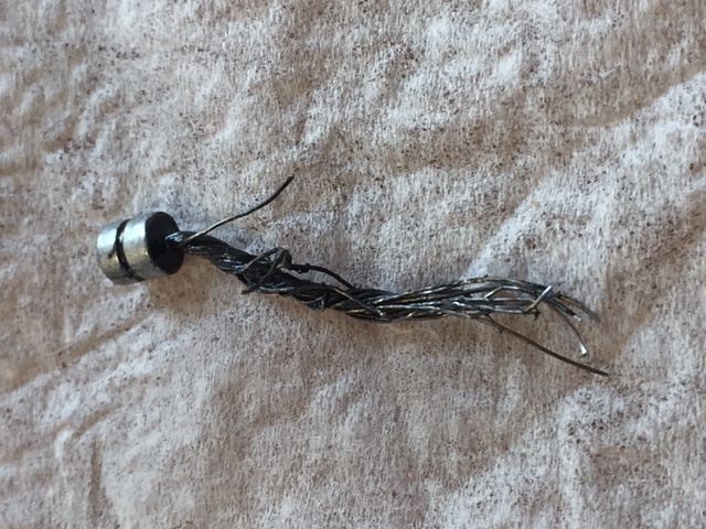
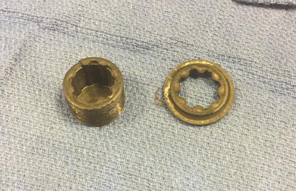
Broken cable from an Ultegra 6600 rear shifter.

Broken 6800
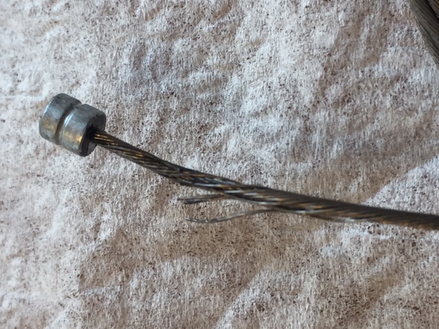
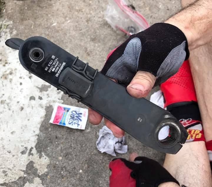
Broken cable from an Ultegra 6800 rear shifter. We mangled this one trying to extract it the hard way, before finding the hatch on the bottom of the shifter that gives easy access to the broken bit.

About to Break
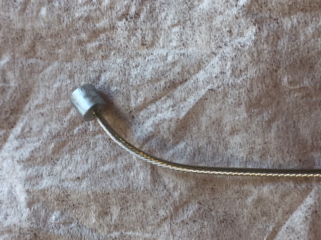
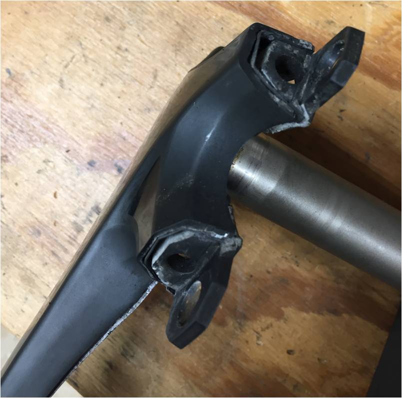
Front shift cable from the same 6800 pair, in the process of failing.

I really don’t feel like I’ve gained much understanding of what’s going on here. It’s possible that near the end of the cable where the strands are rigidly fixed by the head, the cable strands are constrained from moving relative to one another. If so, the cable may act more like a single 1.2mm wire than a 19 strand cable, and it would fatigue a lot faster.

I would welcome thoughts on what’s happening. Anybody?

All said and done, I had a lot of fun. I built a cool machine. I learned to program an Arduino. I did not find a smoking gun. But I’m gonna make a recommendation anyway, based on nothing more than a vague feeling that it might help.

Here’s what you do. Pre-stress the head end of the shift cable into a J shape. This is the shape it is pulled into when it is tensioned.  Pre-stressing it so it naturally assumes this shape may help to equalize the load on the individual strands. Wrap the end of the cable around a pencil or something.

Pre-stressed CablePre-stressed cable

If this sounds similar to the stress-relieving done on spokes before tensioning up a wheel, it should. It performs the same function.

Pre-stressing Spokes Why? How?

I am working on a video version of this post. If you’re subscribed to www.killasgarage.com you’ll get a notification when it’s ready.

Now if you’ll excuse me, I have to go change my shift cables!

Killa

Only in Texas

LoneStar

Is there any other state where residents proudly display their state emblem on the front of their homes? Appropriately this is on the entrance to my garage, not in the front yard.

I submit it as yet another use for old tubes.

Killa

Oh No, Not Another Crank Failure!?

Really, I don’t want to be the guy that spreads pictures of mechanical failures like it’s raining broken bikes. A lot of people experience trouble-free riding. But…

…my good friend Pierre sent me these pictures of a 22 mph crankarm removal.


Crankbolt1Note the dutchman from the bearing preload nut, still screwed into the spindle.

crankbolt2Left crankarm.

crankbolt3Broken bearing preload nut.

I see several learnings here.

First is the obvious failure – the flange broke off of the bearing preload nut and the crankarm came off of the spindle. That nut was supposed to keep the crankarm on, right? No, not really. The only purpose of that lightweight nut is to eliminate lateral play in the crank / bottom bracket interface before you tighten the pinchbolts. It’s functionally like the top cap on your headset. I must admit that until I saw these pictures I thoughtlessly assumed that it was also a secondary retention mechanism. But, slap my forehead, it’s plastic! It is not structural.

The 5mm pinch bolts (“Crankarm Fixing Bolts” in Shimano parlance) are what keep the crank together.

I like Shimano’s pinchbolt crank retention design. 12-14 nm on 5mm pinchbolts is easier to achieve and maintain than 25 or more nm on a tapered spindle design, and it’s less likely to work loose and/or make noise than a tapered spindle interface (in my experience).

Did you ever read the Shimano TechDoc for their cranksets. Quoting:

 The two left crank arm fixing bolts should be tightened at the same time rather than each fully tightened separately. A torque wrench should be used to check that the tightening torques are within the range of 12 – 14 N·m {105 – 122 in. lbs.}. Furthermore, after riding approximately 100km (60 miles), use a torque wrench to re-check the tightening torques. It is also important to periodically check the tightening torques. If the tightening torques are too weak or if the mounting bolts are not tightened alternately in stages, the left crank arm may come off and the bicycle may fall over, and serious injury may occur as a result.

I mean, who re-torques their crank bolts after 60 miles and periodically?

I think it’s really cool that the tolerance between the spindle ID and bearing preload nut is such that you can’t turn the nut after you tighten the pinch bolts. But that led me down an erroneous path of thinking that the nut constituted a secondary retention mechanism. As illustrated in the failure photo it clearly lacks the strength to do any such thing.

If the nut is not a valid secondary retention mechanism, the pin on the little plastic tab – what Shimano calls a “Stopper Plate” – between the pinchbolts surely is not. I’m not really clear on the function of that little tab. I know the pin on the tab drops into a hole in the spindle. Maybe it is an indicator that the crankarm is in the proper lateral position???

So it all comes back to proper torque on the pinch bolts. This is one place I always use a torque wrench (the others being anything that clamps onto carbon). I am also very careful to use a good 5mm head and insert it fully so as not to strip the bolts out. Sometimes this requires that I clean dirt out of the bolts with a pick before inserting my wrench. Rounding out one of those bolts would be the start of a bad day.

Hey Shimano, those pinchbolts would be a great place to use Torx bolts!

By the way, I had a crankset from another manufacturer that used the pinchbolt design, but the spindle didn’t cinch down on the bearing preload nut. I had to regularly – every hundred miles or so – stop and re-tighten the bearing preload nut or it would back out until it hit my ankle. I eventually drilled a small hole in the flange of the nut and safety-wired it in place. I was under the apparently false assumption that it would have prevented the crankarm from coming off if the pinch bolts loosened up.

So grab your torque wrench and go check your crank!

I refuse to discuss the JRA (Just Riding Along) failure of a titanium frame,  pictures of which Pierre also sent me.

Tailwinds

Killa

Musings on Shimano HollowTech Cranks


I was wondering the other day about Shimano HollowTech cranks.

How do they make them hollow?

How hollow are they?

I learned the answer to my first question when my friend Kara brought over her bike and said “There’s something wrong with my cleats or maybe my pedals. They feel spongy.”

Broken Crank Spider

There was nothing wrong with her pedals or her cleats. Inspection of the crank revealed separation between the inner and outer surfaces of the right crankarm in the spider area. In simple terms, it came unglued. By the way, although Kara is a strong rider, she weighs maybe 120 lbs, so this is not a simple case of excessive torque. Larger riders apply much more power than Kara through identical cranks.

I thought this was a weird failure mode, so I Googled “Ultegra 6800 crank failure”. I found that while not common, it is not unheard of. Good move on Kara’s part, sensing that something was wrong before the separation led to a completely severed crankarm.

I’m not bashing Shimano here. Google “Broken Bicycle crankarm images” and you’d think these things – any brand – are falling apart left and right.

Today’s post is not a root cause analysis. I don’t know why Kara’s crank failed. Maybe the glue was out of spec. Maybe she crashed on it. Maybe some kind of solvent or some environmental factor destabilized the glue, maybe it was assembled on a humid day…

Anyway, now I know, Shimano makes their HollowTech cranks hollow by bonding two halves of a “clamshell” together with what for lack of a better word I will call glue. They also make their outer chainrings hollow. On the chainring you can see the bond line between the two elements. It is much more difficult to identify the seam on a crankarm. You can see a squirt of excess glue on the inside of the spider.

My first reaction was “Glue? Really?” But wait a minute. My entire carbon fiber bicycle is nothing but carbon fiber cloth and glue. Heck, NASA used glue to hold the space shuttle together…. Never mind. My point is that using an engineered glue is a valid assembly process.

Remember when I described using a heat gun  to loosen a stuck pedal. I said that on a carbon fiber crank you need to be careful with heat. I would apply that warning to a HollowTech crank as well, because I don’t know what the temperature rating of the glue is. If you can’t hold it in your hand for a few seconds, it’s probably too hot.

Making crankarms hollow is a very effective way to reduce weight without sacrificing rigidity. Rather than go all technical, I’ll just point out that your whole bicycle is made of hollow tubes for exactly this reason. The trick is manufacturing a hollow crankarm. Shimano’s bonded clamshell solution is elegant, but obviously dependent on the integrity of the bonding agent (glue).

I also was wondering how much weight is saved by going hollow? Calculating specific gravity turns out to be an easy non-destructive way to determine how much aluminum is missing from the interior. I decided to evaluate a left crankarm only, mostly because a right crankarm with the spider wouldn’t fit in my graduated cylinder.

GossameronScaleUltegraonScale


The specific gravity of aluminum is ~2.7 gm/cc. By measuring the weight and displacement of a solid crank I can determine the specific gravity of the alloy used.

By measuring the displacement of a HollowTech crankarm and its weight, I can calculate an effective specific gravity, which it turns out is significantly below solid aluminum. In the table below I compare a typical solid construction crankarm (FSA Gossamer) to a HollowTech crankarm.

GossamerinWater UltegrainWater


A few comments on the above photos. That’s not Mountain Dew; it’s just water with a few drops of food coloring. Before you tell me my displacement numbers don’t add up – I started with different amounts of water in the graduated cylinder for the different cranks.

Table

My FSA sample is 175mm; my HollowTech is 170mm, so my analysis unfairly favors the HollowTech design by a few grams. An eyeball estimate suggests that shortening the gossamer crank by 5mm would remove about 2 cc’s or 5.5 grams of material.

We can calculate that if a HollowTech crankarm was solid, it would weigh an uncompetitive 306 grams, assuming the same density alloy is used as the FSA.

Is the HollowTech crankarm stiffer? According to everything I learned from Dr. Carver at LSU 43 years ago, it has to be, if it is made out of similar material. By moving material out away from the central axis of a beam, you increase both the area and polar moments of inertia; the beam (crankarm) becomes more resistant to bending and torsion. Can you feel the difference? I don’t know. Is the difference even detectable? I don’t know, but I think I’ll do some calculations and run a test if I can devise a way to rigidly anchor the spindle end of the crankarm.

Until then, Tailwinds!

Killa

Tire Width and Rim Stress, a Video Demonstration


I was working on a post about shift cable fatigue and fraying when I became distracted by a Lennard Zinn Technical FAQ discussion in Velonews about tire width and rim stress. As an engineer I know that a wide tire imposes higher forces on a rim, specifically lateral force on the sidewalls, than a narrow tire – at any given pressure.

I found the various explanations put forth by Lennard and some of his readers confusing, so I drafted a response invoking the hoop stress formula, etc. But I decided that instead of another explanation I would perform and video a visual demonstration of rim deflection as tires of different widths are pressured up to 100 psi.

Wide tire proponents will argue that running a wider tire allows use of lower pressure. OK, I agree. I am demonstrating that, all else equal, the wider the tire, the more rim stress. (I did take one set of measurements to determine how much pressure reduction would be required in a 32mm tire to induce stress equal to 100 psi in a narrower tire, like a 23mm or 25mm; keep reading).

Oh, by the way, I’m talking about clincher tires and rims. And I am addressing the forces on the rim, not the forces in the tire casing – though I maintain that the forces in the tire casing also get higher as tire size increases.

Anyway, as you pressure up a tire, the tire drives the rim walls away from each other. The rim gets a tiny bit wider. So I rigged up a test apparatus with my Park Tools wheel truing stand and a dial indicator. I measured rim deflections as I pressured up 23mm, 25mm, and 32mm tires to 100 psi, each on the same wheel. It turns out that the change in width is quite measurable, on the order of up to .030” (thirty thousandths of an inch).

In a video that is sure to be nominated for academy awards in several categories, I documented my work and posted it on Killa’s Garage YouTube.  If you don’t want to watch a really cool five minute video, complete with the sound of my compressor kicking on while pressuring up the 32mm tire, here is a table of key results.

Rim

Rolf Prima Vigor

Tire 23mm Conti 4000 S ii 25mm GatorHardshell 32mm Specialized All-Condition
Tire Actual Width at 100 psi 23.6mm 23.9mm (This surprised me) 32.0mm
Rim Deflection at 100 psi* .017” .019” .027”
Rim Deflection at 80 psi* Not recorded Not recorded .018”

*Deflection values are rough averages of several pressure cycles. But I was gratified to observe that even with my primitive apparatus, values for each set of conditions varied no more than +/-.001”.

If these deflection values seem high, keep a few things in mind:

  • The rim I used is a fairly lightweight racing rim. I tried this with a heavy (thick-walled) inexpensive rim from a cheap hybrid and got less than .010” sidewall deflection with the 32mm tire at 100 psi.
  • My methodology measured the total deflection of both sidewalls. In other words I measured the total rim width change.
  • This is the deflection at the outer edge of the rim.
  • The deflection returned to zero when the pressure was removed, showing that the elastic limit of the rim was never exceeded.
  • This is why you need to pay attention to the minimum thickness marks on the braking surface of your rims.

Here is a bar chart of my results … for people who prefer bar charts.

Stress Chart

And a summary of results … for people who prefer summaries.

The measured width of my 23mm and 25mm tires are very similar, as are the induced rim deflections. The 32mm tire is much wider and it induces a much higher rim deflection at the same pressure. However, if you can run your 32mm tire at 80 psi you induce deflections similar to the narrower tires at 100 psi.

I can see utility in doing some further testing. I could evaluate different rims. I’d like to see how a full carbon rim responds. But I’ll leave that for another time.

Now if I can come up with a device to fatigue test shift cables I can answer the question I was working on when I got distracted by tire width and rim stress.

Thanks for reading

Killa

Upper Headset Bearings Last Forever, Except When They Don’t


If I had a nickel for every time I said that upper headset bearings never wear out, I’d have… a few bucks anyway. Upper headset bearings usually do last a very long time. Lower headset bearings take all the pounding, and they are located in the second dirtiest area of a bike, at the top of the fork where the front wheel sprays up road grime.

The dirtiest area is at the back of the bottom bracket. (Hey, let’s mount the rear brake there!) But this is a story of headset bearings, not bottom brackets and brakes.

A friend showed up in the garage recently with his tri-bike. It had serious problems, not least of which was a rear bar-end shifter that went slack in the middle of a full Ironman, requiring him to ride the remainder of a hilly bike leg on the 11 cog. And also not least was a completely seized rear brake mounted guess where? But this is a story of headset bearings, not shifters and brakes, so on to headset bearings. Continue reading “Upper Headset Bearings Last Forever, Except When They Don’t”

Help, I Can’t Get My Pedals Off!

Forty three years ago I worked a summer as a roustabout on an oilfield work gang. A large part of my job those months was operating a 48” pipe wrench to tighten and loosen threaded connections of all sorts. The senior guys on the crew watched me struggle for a few days (to build character, I guess) before sharing their “secrets”. Some of what they taught me is not applicable to bicycle mechanics, like beating on a corroded flowline thread with a sledge hammer to loosen it. But a lot of the principles of wrangling threaded connections apply.

Bicycle pedals are notorious for being hard to remove. One reason is that they self-tighten as you pedal.  This is a good thing – they tend not to fall off. This is why the left pedal has a left-hand thread. Unfortunately this self-tightening effect, along with a bit of corrosion, can make them very difficult to remove, even if they were not over-tightened during assembly.

It gets worse. Many manufacturers have eliminated the wrench flats to shave off a few grams. A 6mm or 8mm allen key must be inserted into the end of the spindle. Try getting any leverage in this position!

allen key pedal

Over the years I have attacked a lot of stubborn pedals, and I have learned some tricks that have enabled me to remove pedals that no one else could. Continue reading “Help, I Can’t Get My Pedals Off!”

Centering Dual Pivot Brake Calipers the Right Way


duraace-brake

Shimano dual pivot brake calipers are nice little machines, as are calipers from most other manufacturers that copy the dual pivot design. I say copy. I actually don’t know who invented the dual pivot brake. Shimano certainly popularized it.

They’re compact, stiff, and powerful enough to fully utilize the rim/brake pad interface, meaning you can skid the back tire or throw yourself over the bars with the front brake. You don’t need any more power than that. Don’t get me started on the rim brake vs disc brake discussion.

On the downside, they are limited to about 28mm tires. If you tried to scale up the design to clear a larger tire, it would be too flexible, unless you increased the thickness and weight of the arms unacceptably. Tire clearance is why cross bikes with larger tires use other brake designs, such as cantilevers.

One cool feature of dual pivot brake calipers is that they return to the same position every time they are released. Well, this is cool if the position they return to is correct. What if it’s not correct? One way to fix this is to grab the whole caliper and rotate it into position. This works, but it’s not very accurate, and it loosens up the attachment to the frame, making it more likely that the brake will move out of position next time you bump it with your foot or remove/insert a wheel.

There is a better way to center your brake calipers and it’s built right into the brake. Every dual pivot brake caliper I have seen has a “lateral adjustment screw” whose function is to shift the brake pads to the left or right. It is usually a 3.0 mm allen head screw that is accessible from the top or side of the caliper. Contrary to popular belief, this screw is not for adjusting the distance between the pads, although it does seem to have a minor effect in that regard.

oldbrakecaliper2duraacebrake

The lateral adjustment screw is easy to find on older brakes. It is more tucked away on the latest generation.

So here’s how I center my brakes:

  1. Screw the lateral adjustment screw all the way in, then back it out about four to five turns.
  2. Loosen the caliper mounting bolt, usually a 5 mm allen. (Campy uses a T25 torx bolt – of course)
  3. Center the brake approximately, and re-tighten the mounting bolt firmly. Shimano’s spec is 8-10 Nm.
  4. Rotate the lateral adjustment screw to balance the pad clearance between left and right sides.
  5. Re-adjust the total pad clearance if required with the cable adjustment nut.

One final note: The brake release levers are for wheel removal and insertion. Using the levers for pad clearance adjustment is like fingernails on a chalkboard to a mechanic.

brakereleaselever

Brakes should be adjusted with the cable adjustment nut so that the pad clearance is correct when the release lever is all the way down. The only time you should ride with the lever other than down is if you have crashed or broken a spoke or something and you are trying to get home with an out of true wheel.

Thanks for reading!

Killa